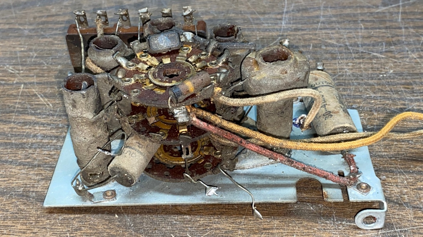
Having successfully rebuilt the antenna section of the 37-116 RF unit, it was time to try rebuilding the converter or RF section. As you can see in this first photo, the RF section was even dirtier than was the antenna section. I felt more confident this time, since the antenna section did not really seem to be all that difficult, just time consuming.
This time, I did devise an additional key or “road map” before I began to disassemble this section:
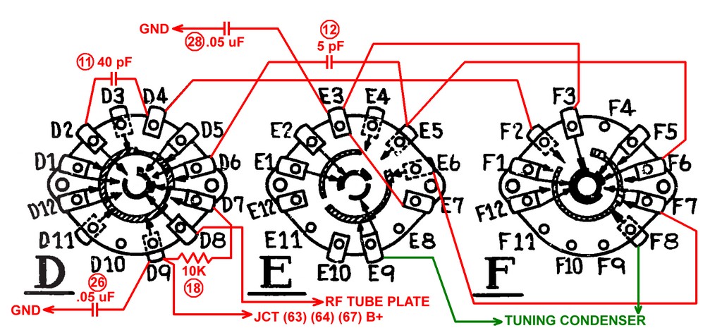
Drawing which shows the various connections to, and within, the RF section switch wafers.
This shows all the capacitors, resistors and wires which connect to, and within, these three switch wafers of the converter or RF section. It does not show the wires which connect from switch wafers to the trimmer condenser assembly; the schematic, plus the illustration of the trimmer condenser assembly, should suffice for these wires.
The other keys or “road maps”, including the partial schematic and the illustration of the trimmer condenser assemblies, may be found in Part 4 of this series.
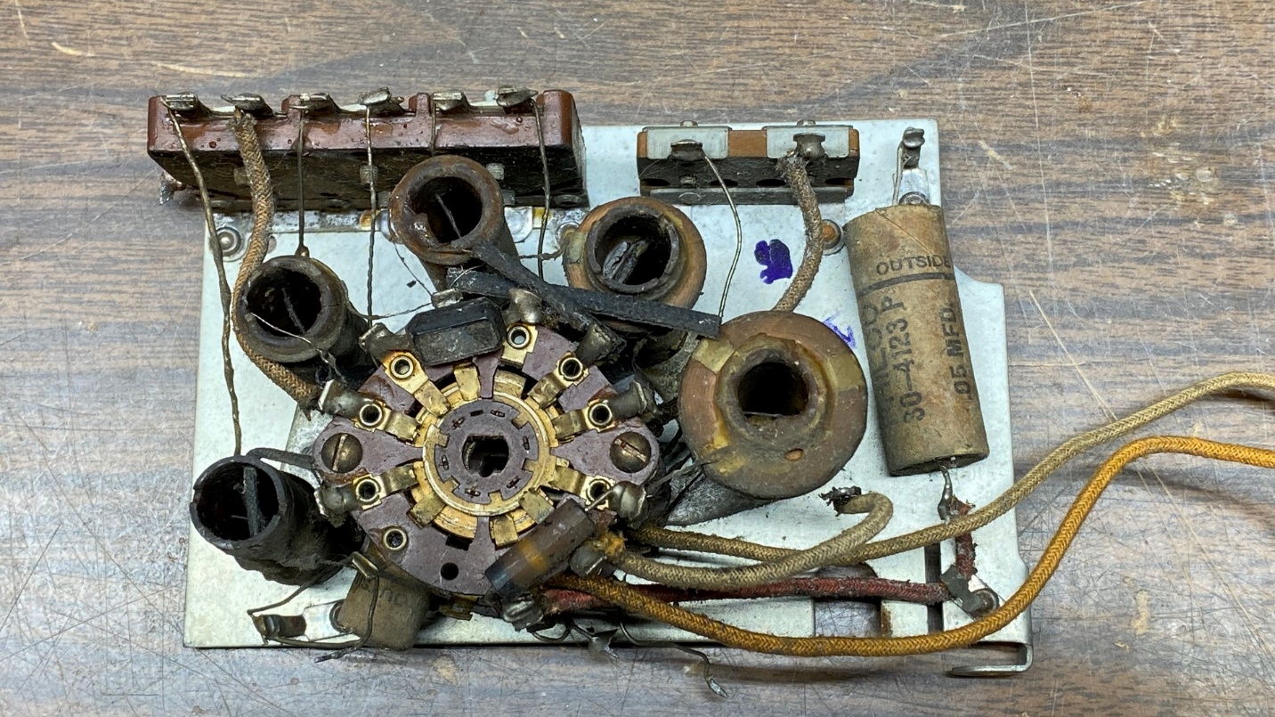
Another look at the RF section before disassembly.
Disassembly of this section was much like the antenna section, so I did not take as many photos. As before, it is important to take your time and make sure you have fully documented everything, as I have tried to do here and in Part 4 of this series.
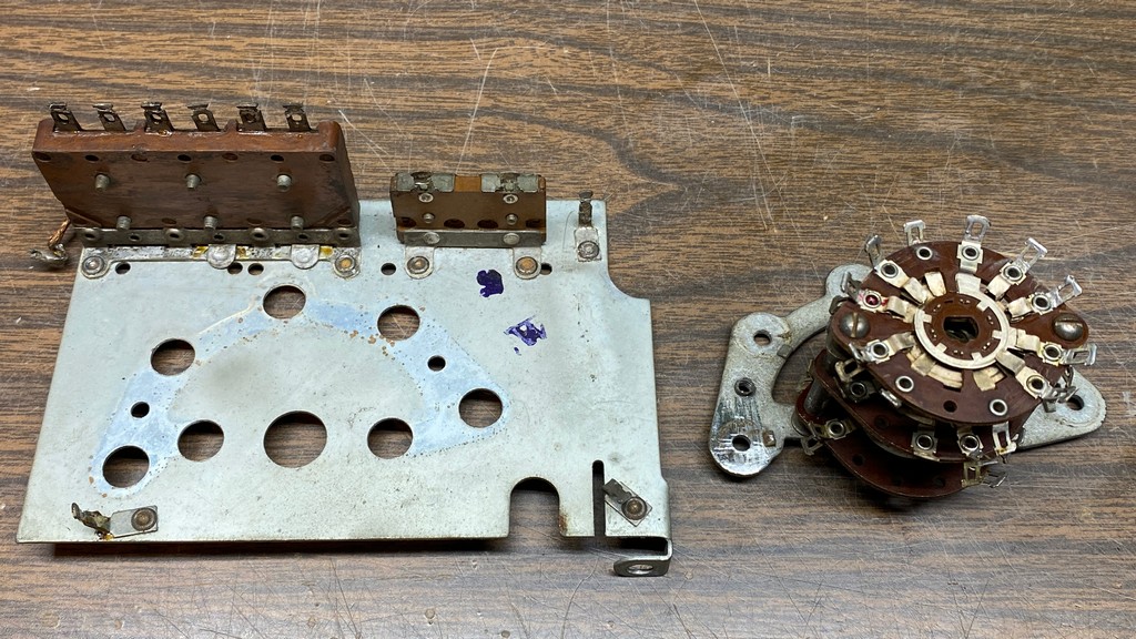
Showing the bare RF assembly after removal of coils, capacitors, resistors, and all wiring.
Once everything was apart and the switch wafers separated, these were carefully inspected for any signs of carbon tracks. Finding none, I then cleaned the switch wafers with 91% isopropyl alcohol, then reassembled. I have since purchased some 99% isopropyl alcohol strictly for cleaning jobs just like this. The 99% isopropyl arrived only two days after ordering, so I will be using it for the oscillator section switch wafers once I get to those.
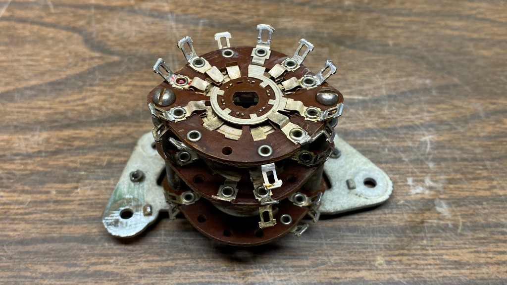
The switch assembly after disassembly, cleaning, and reassembly.
After putting the switch wafers back together, it was a matter of first installing new capacitors, resistors, and wires, and then reinstalling the coils, one by one.
The RF unit used two tiny mica capacitors, a 5 pF and a 40 pF. These were replaced by a 5 pF silver mica and a 39 pF NP0 ceramic disc, respectively. I used capacitors I had on hand to avoid having to make a special parts order.
As before, the coils were baked for 30 minutes at 200 degrees Fahrenheit to drive out any residual moisture. They were then all tested for continuity before being reassembled onto the switch assembly. All five checked out OK.
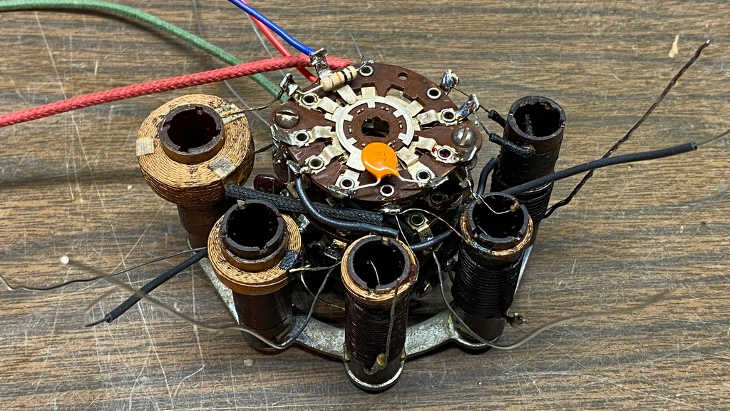
The reassembled switch assembly, ready to attach to the trimmer condenser assembly.
Once reassembled, the switch assembly was reattached to the plate holding the trimmer condenser assembly. Then the various wires were resoldered to their proper points on the trimmer condenser assembly.
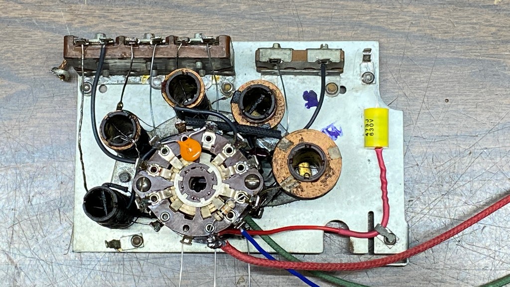
The converter or RF section, completely cleaned and rebuilt.
After everything was back together, I double-checked the coils for continuity. All was well.
And that is all there is to it. This converter or RF section is now ready to be reinstalled onto the sub-base of the 37-116 RF unit.
Next up: The most difficult section of all – the oscillator section.