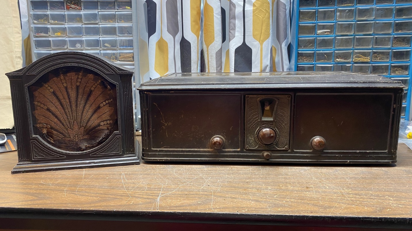
My Philco Model 65 radio is all finished and works again after, likely, decades of silence. Now I would like to get its companion F-10 speaker going again. As you may recall, I actually have two of these speakers. My plan is to end up with one working speaker, even if I must use ingredients from both speakers to reach that goal.
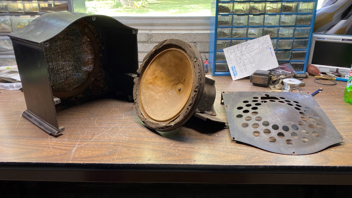
Disassembled F-10 speaker. The bottom cover is not shown here.
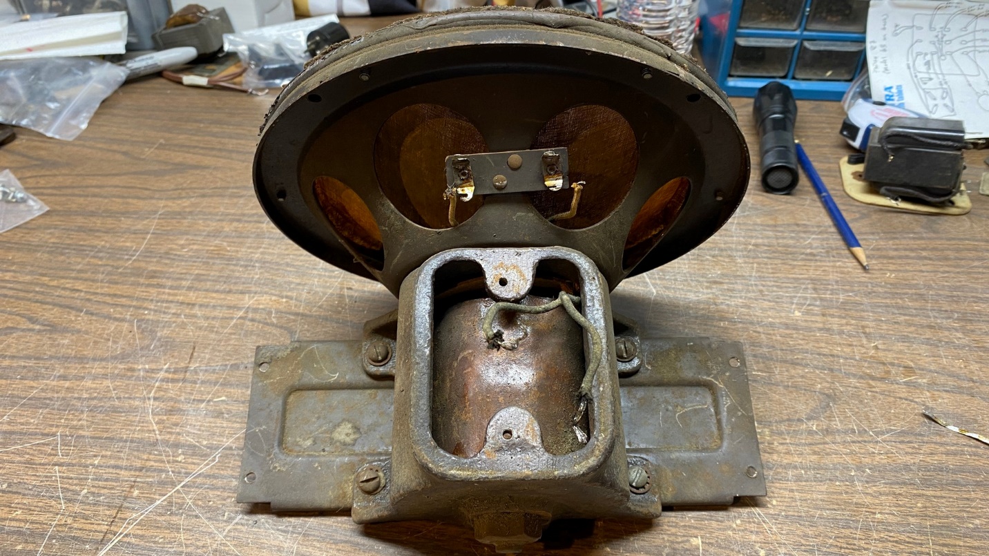
The F-10 speaker cabinet with driver removed.
I decided to disassemble the F-10 speaker that had the grille cloth which had been replaced at some time in the past. To remove the driver from the cabinet, you must first remove the metal back, and then the fiberboard bottom cover. Both pieces are held in with screws.
Once this is done, the four screws that hold the driver inside the cabinet will be accessible. Remove these, and then carefully pull the driver out of the cabinet as shown above.
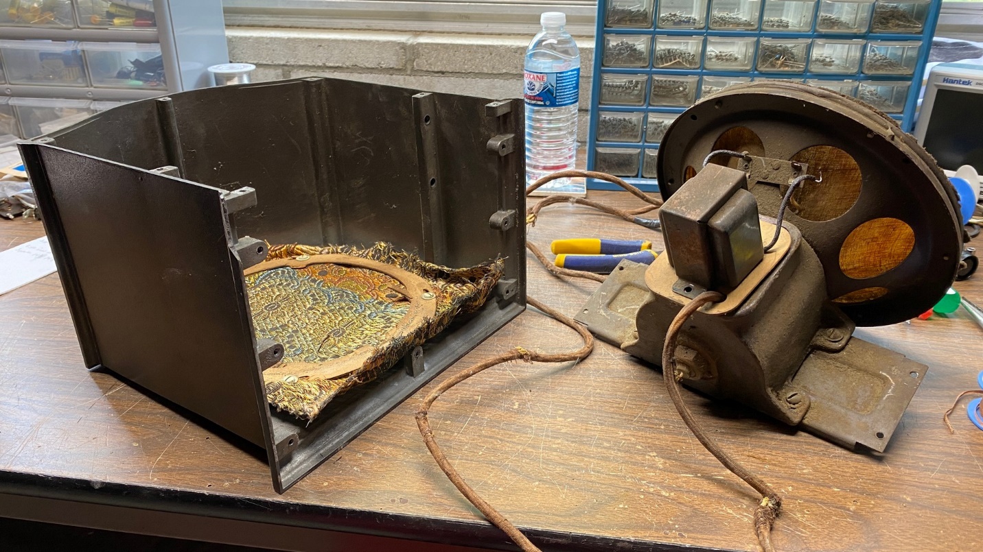
Here, I have removed the dead audio output transformer from the speaker assembly. The four-conductor cable is still attached to the transformer’s terminals.
This speaker not only had an open field coil, but also an open audio output transformer. The only good thing about this speaker was its voice coil. So, a lot of work is going to be required to get this speaker back into working condition.
In case you’re wondering about the other F-10, it also has a bad field coil and bad audio output transformer.
The next thing I did was to remove the audio output transformer. I unsoldered and removed the leads which run from the speaker voice coil terminals to the audio transformer. Following this, I removed the two screws which fastened the audio transformer to the speaker assembly, after which the transformer was removed.
The speaker cable of this F-10 was eight feet long! I have no intention of using this speaker far away from its companion Model 65 radio, so I put together a new speaker cable using four cloth-covered wires. I made each wire five feet in length. By the time everything is reassembled, the cable will be roughly four and a half feet in length.
On the other end of the cable, there is a large four pin speaker connector which plugs into a matching socket in the Model 65 radio. Philco used this same speaker connector in all their 1929 model radios.
Unfortunately, this connector was broken, and one of the four pins was completely disconnected from the connector.
Having nothing to lose, I decided to see if I could salvage the connector.
This speaker connector uses two sheets of fiber. One sheet has the four pins staked into it; the other sheet is used as a cover. The two sheets were originally riveted together with four rivets.
I undid the four rivets and then separated the two fiber sheets. Then, using J-B Weld, I glued the loose pin back onto the sheet which had the pins staked in place. Once dried, the J-B Weld filled in the missing piece of fiber which once held the loose pin in place.
By the way, J-B Weld is nonconductive! I used this glue as I wanted the repair to be strong.
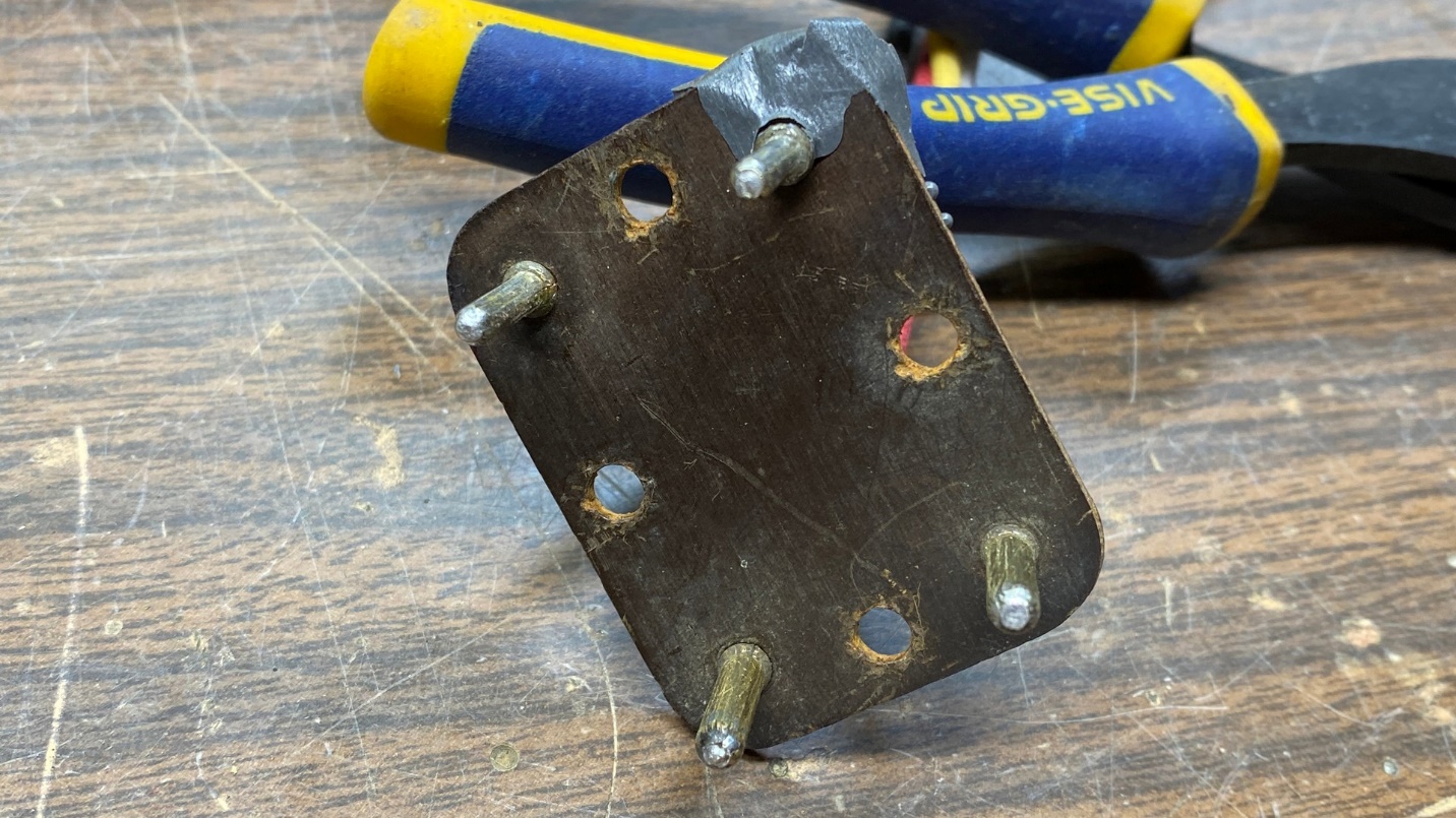
Part of speaker connector with once-loose pin glued back into place.
After the glue was dry, I trimmed away the excess glue and soldered the four new wires to the pins, and then put both fiber sheets back together, with the four spacers and four original rivets to help hold everything together. I used more J-B Weld to hold it all together, using small C-clamps to hold the connector together until the glue was dry.
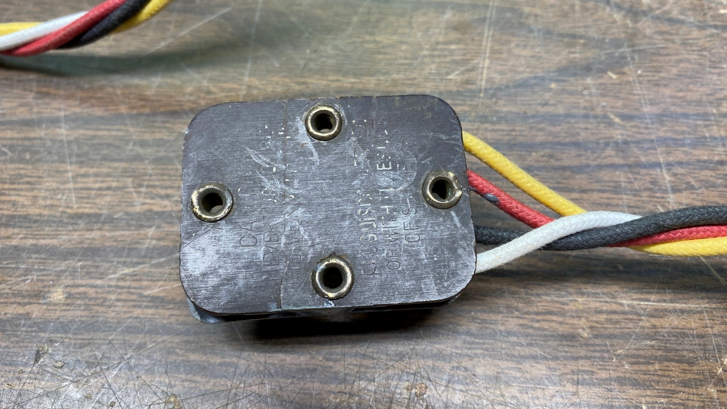
Top view of repaired speaker connector.
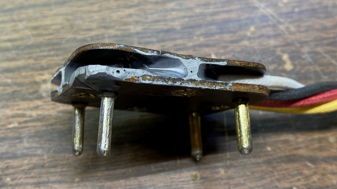
Side view of repaired speaker connector.
Sure, it looks a bit sloppy, but it is functional and is better than having a broken speaker connector.
Now that I had a usable speaker connector with a new four-wire cable, I set this assembly aside for the time being, before turning my attention back to the driver.
I was aware that the Alabama Historical Radio Society would rewind speaker field coils. I contacted them and was advised to remove the old field coil and send that to them.
This meant that I was going to have to mostly disassemble the speaker. Had it not been for the fact that I have taken early Philco speakers apart in the past, I don’t think I would have tried this. It is not an easy job, and it must be done in a certain order to not damage or destroy the speaker.
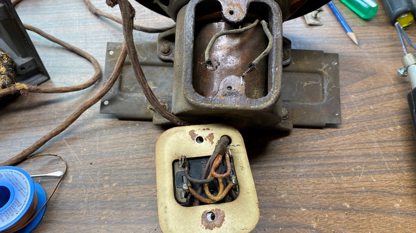
Philco F-10 driver showing the speaker field coil inside the “pot”.
In order to remove the speaker field coil, the following things must be done, in this order:
- Unsolder and remove voice coil wires from terminal strip on back of driver.
- Remove speaker gasket from front, if used.
- Remove speaker cone trim ring.
- Remove speaker cone.
- Remove nut holding pole piece from back of speaker.
- Remove pole piece.
- Remove field coil.
Reassembly will be the reverse of disassembly.
A word of caution: Do not, absolutely do not, attempt to remove the nut from the back of the speaker until the speaker cone is removed. I once destroyed a good Philco 20 speaker cone by doing this.
This is going to be a lengthy procedure and I’ve already used up a fair amount of space here, so I will continue with this disassembly in the next installment. Stay tuned!