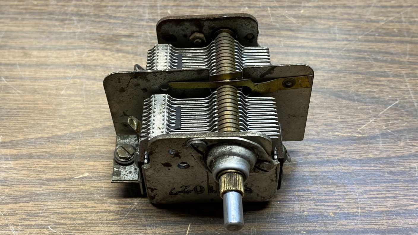
Last time, I had begun to reassemble the Philco model 54C radio chassis and was almost ready to install the tuning condenser. Unlike its siblings (models 53, 57, 58 & 59), model 54 used a ball bearing reduction drive which allowed the radio to be tuned more slowly as the tuning knob was turned. The other Philco cigar box pee-wee models all used direct drive tuning, which is harder to use when tuning in stations.
All the vintage ball bearing drive mechanisms use grease inside, and that grease hardens up over time and becomes ineffective. In this case, when the tuning shaft was turned, sometimes the tuning condenser would respond, and sometimes not. So, I needed to remove the mechanism and address that issue before I reinstalled the condenser in the radio chassis.
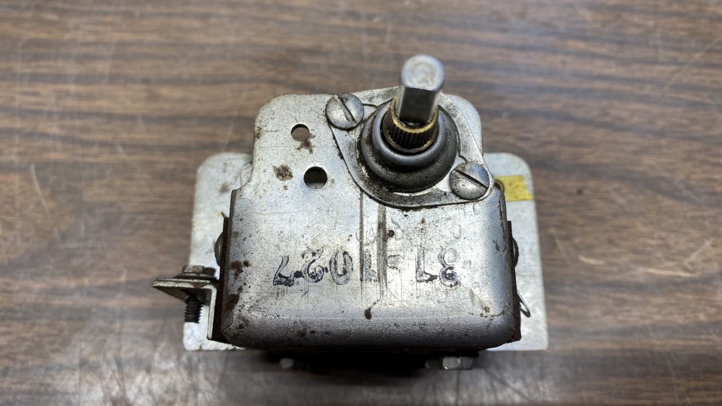
The dial drive mechanism is held in place with two screws as shown above.
The mechanism is easy to remove. Simply remove the two screws which hold it in place. But do be very careful if you do this, as there are three ball bearings inside. You do not want to lose them!
I removed the screws, and then carefully pulled off the cover. I made sure I had plenty of room on the workbench so I could catch any ball bearings that might try to escape. Fortunately, they stayed in place until I pulled the tuning shaft off. At that point the bearings were easily removed.
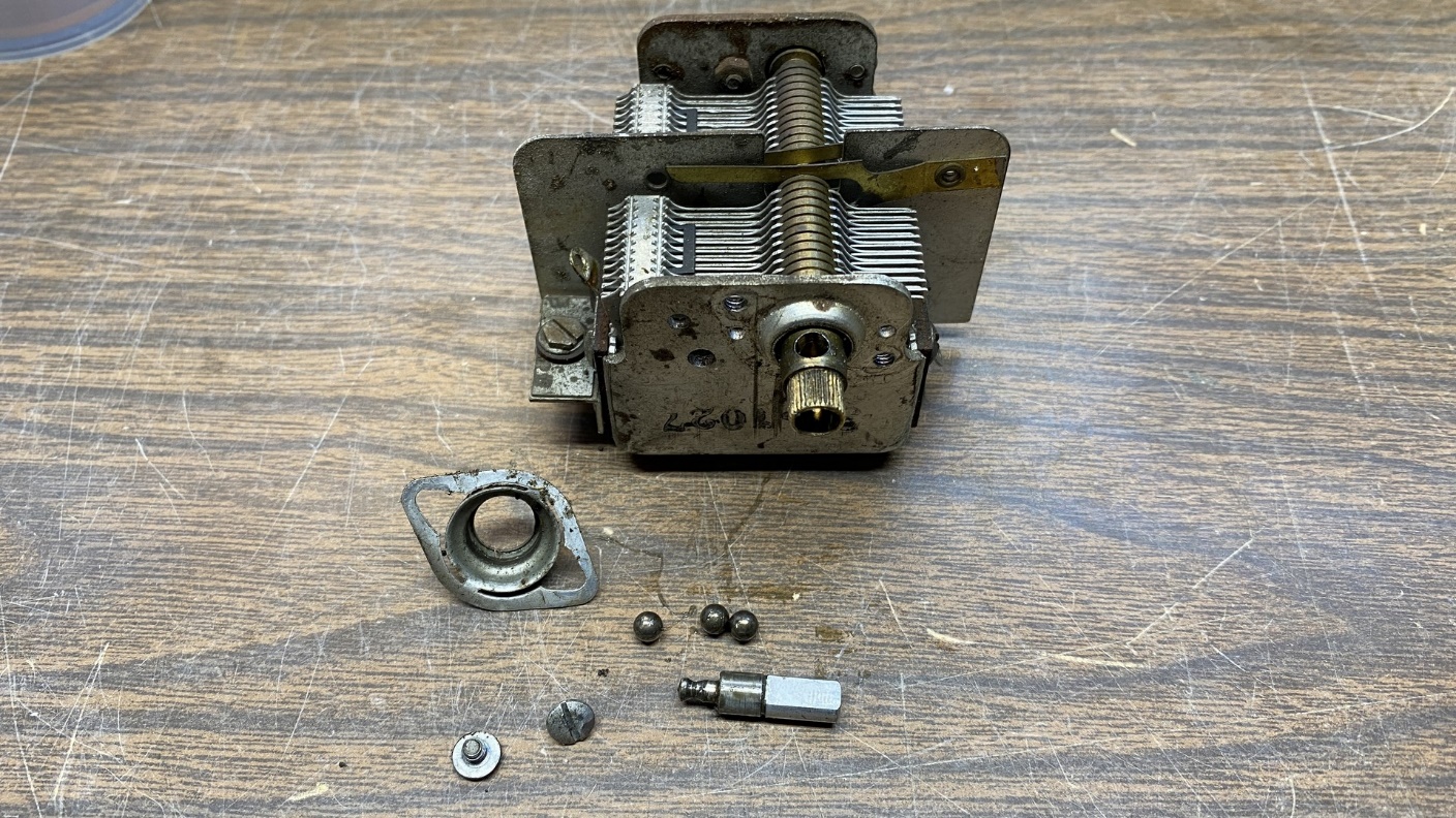
The ball bearing drive mechanism has been removed from the tuning condenser.
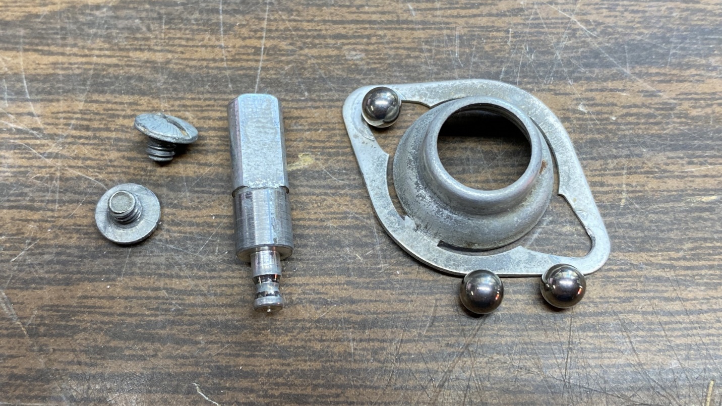
Some larger radios, notably the mid-1930s Philco and RCA sets with dual tuning shafts, used one or two smaller ball bearings and a spring in addition to the three main ball bearings. This was not the case here. This simple mechanism consisted of a tuning shaft, three ball bearings, and a metal cover.
Let’s take a closer look.
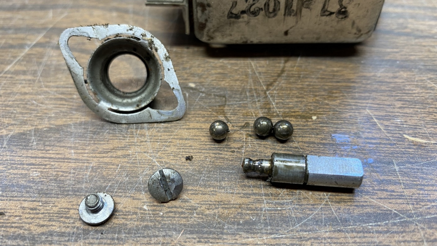
The parts which make up the dial drive mechanism.
In the photo above, you can clearly see the residue of the old grease on the tuning shaft and the ball bearings. These parts need to be cleaned. I chose to soak the parts in Naptha for a few hours.
After soaking, I carefully wiped everything down, and then the parts looked like this:
Dial drive parts, all cleaned up and ready for reassembly.
The next job was to reassemble everything. I began by applying white lithium grease to the main tuning condenser shaft where the ball bearings sit in place and where the driving end of the tuning shaft sits and makes contact with the bearings. I then put the bearings into the three holes in the main tuning condenser shaft. The grease keeps the bearings in place while I take care of the rest of the assembly.
See the photo below for more details.
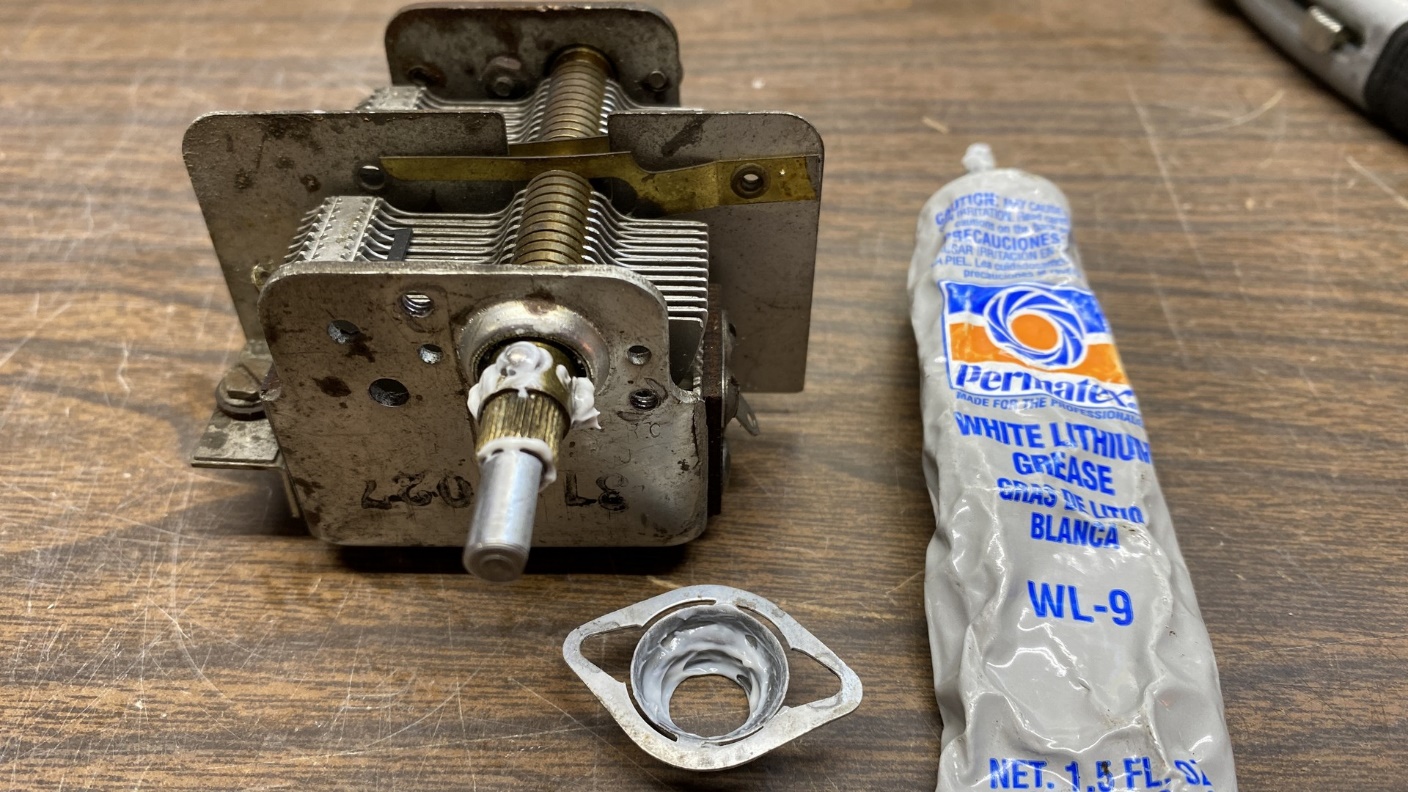
The tuning assembly is reassembled with the help of new white lithium grease.
Here, you can see the ball bearings sitting in grease. The tuning shaft is also back in place. Notice I have also applied grease to the inside of the cover.
Finally, I reattached the cover to the tuning condenser, making sure everything remained in place as I did so.
At this point the tuning condenser looked like this:
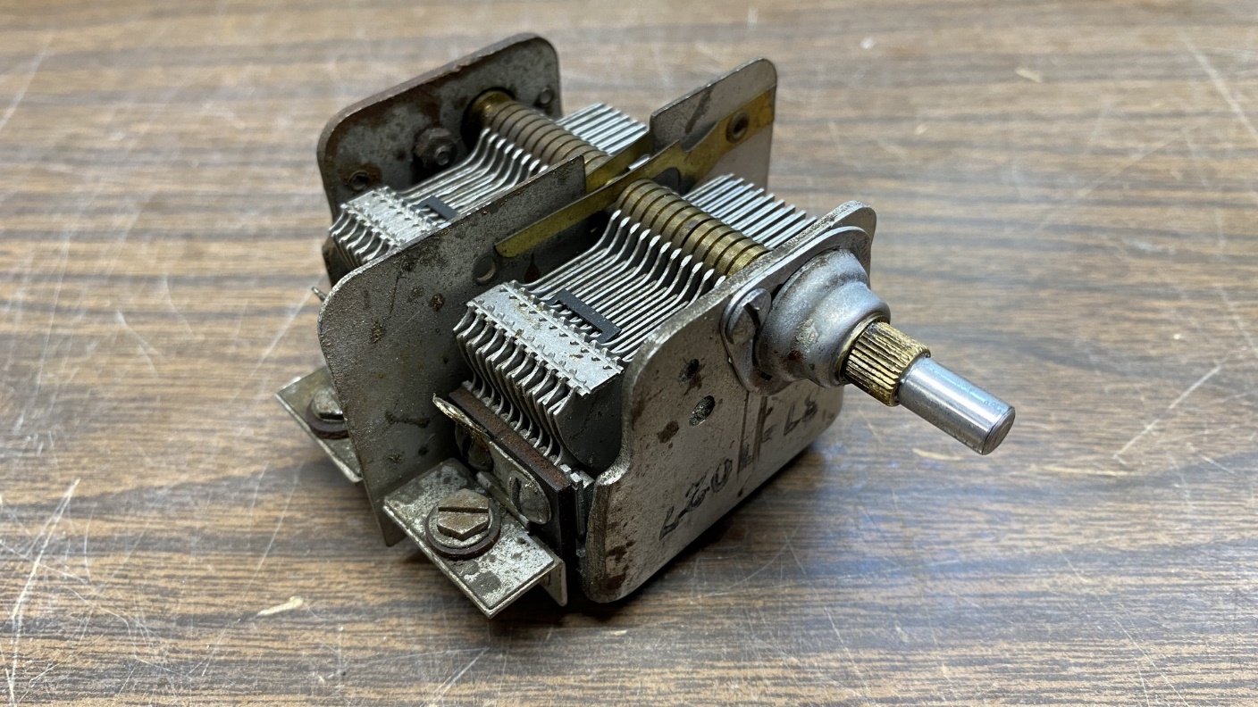
The reassembled tuning condenser, ready to be reinstalled in the radio.
I tried the mechanism out. Tuning felt smooth again, and the condenser properly opened and closed as it should.
After testing the mechanism, I reinstalled the tuning condenser into the radio chassis.
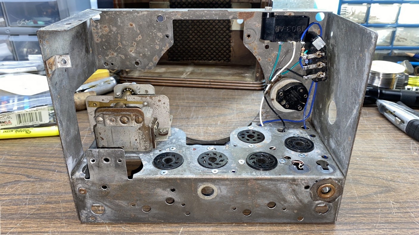
The tuning condenser is now back in the radio chassis.
Soon after this, the custom-made electrolytic cans arrived from my friend. These cans were originally Sprague Twist-Lok electrolytics. They had the wider bottom ends cut off and emptied out, and my friend also made plastic press-in plugs for the bottom of each can. Using a drill press, he also drilled the necessary holes so that I could make new terminals for these.
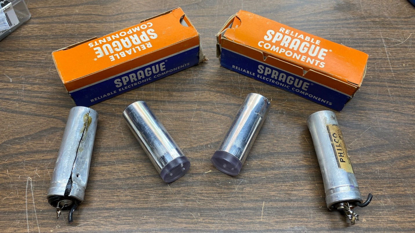
Custom replacements (center) for the original electrolytic capacitor cans (left and right).
In the next post, I will illustrate how I made new terminals for these cans, installed them into the radio chassis, and did a little more work. Please make it a point to join me then.