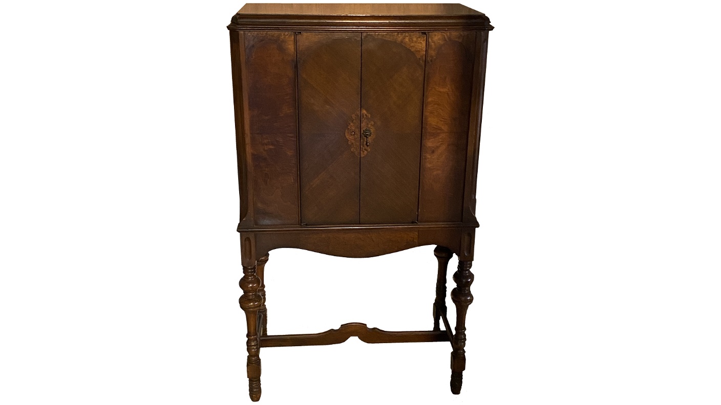
A good friend of mine, upon learning that I had never owned a 1929 Philco highboy, brought his model 87 highboy to our house last year. The cabinet (which you can see in the photo above) is in very good shape with excellent original finish. One of the door pulls is missing, but I can eventually replace that.
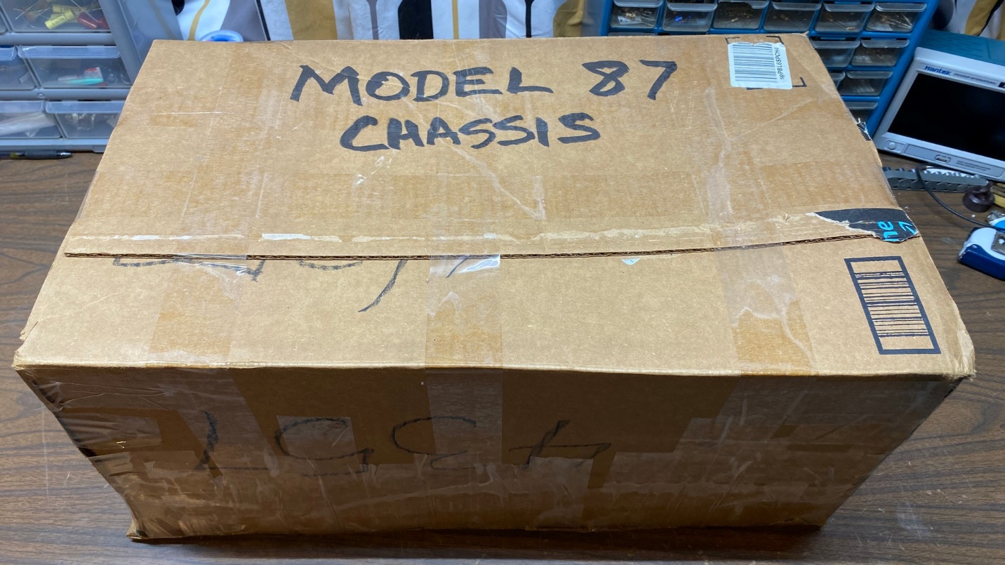
My friend had packed the chassis of this Philco 87 quite well for its journey from Pennsylvania to Indiana.
In gratitude, I picked out one of my radios and asked my friend to take it home with him. It turned out that this particular radio I offered him was one that he had really been wanting, so we both ended up happy with our new acquisitions.
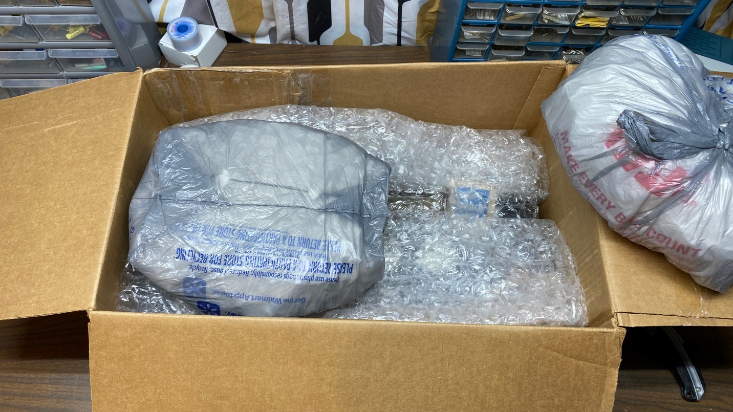
Looking inside the box.
This past week, I finally pulled the box containing the 87 chassis out of storage, opened it up, and put it on my workbench.
The Philco 87 is the third and final generation of Philco’s “Neutrodyne-Plus” radio receivers; the first generation being Model 511 and its siblings, the colorful metal box Philcos of 1928 along with lowboy and highboy console versions; and the second generation, Model 86, a slight refinement of Model 511 which was sold in early 1929.
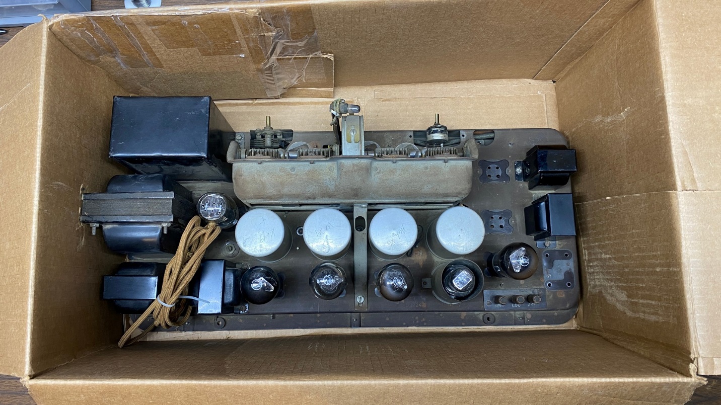
The Philco 87 chassis inside the box.
Model 87 was introduced in June 1929 and was only available in console form (lowboy, highboy and a “Highboy De Luxe” which had sliding doors). It sold well in lowboy and highboy formats and is easy to find today.
All of Philco’s “Neutrodyne-Plus” radios are very simple in design. In reality they are not far removed from the design of the three dial TRF and Neutrodyne radios of the early to mid 1920s. When properly restored, however, they are surprisingly good performers and very sensitive as well.
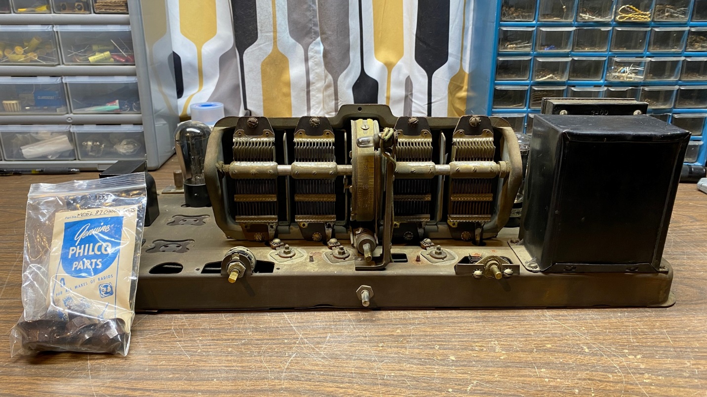
The 87 chassis on my workbench. The knobs and mounting bolts are in the little bag at left.
I put the heavy (around 50 lbs.!) chassis on my workbench and looked it over. It had six of its eight tubes; only the 45 output tubes were missing. I have some 45 spares so that will be no problem to replace those. I removed the tubes, turned the chassis upside down, and removed the bottom cover. I immediately noticed that one of the three combination capacitor-resistor modules was missing. These modules, with their tubular housing made of fiber or sometimes Bakelite, were the precursors to the “Bakelite block” capacitors which Philco began to use in mid-1930.
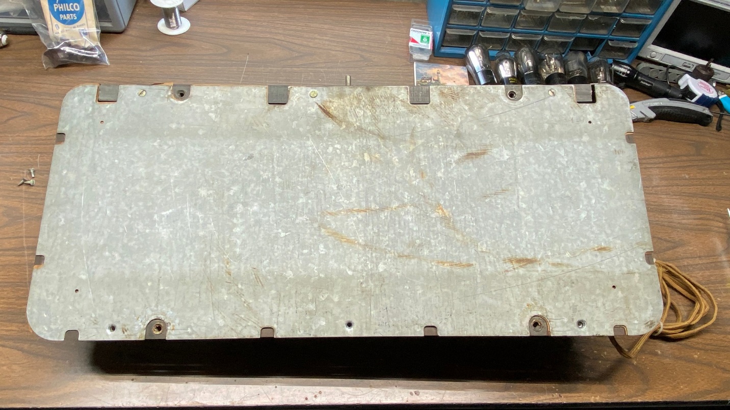
Underside of the 87 chassis, with bottom cover in place.
I also noticed a great deal of wax under the second audio interstage transformer. Grabbing my digital multimeter, I made tests on the components which I expected to have issues. I found that all four coils were good – surprise! The three-section tubular resistor had one open section – not a surprise. And both audio interstage transformers had open primaries – also not a surprise, especially considering all of that wax which had melted out of the second interstage transformer.
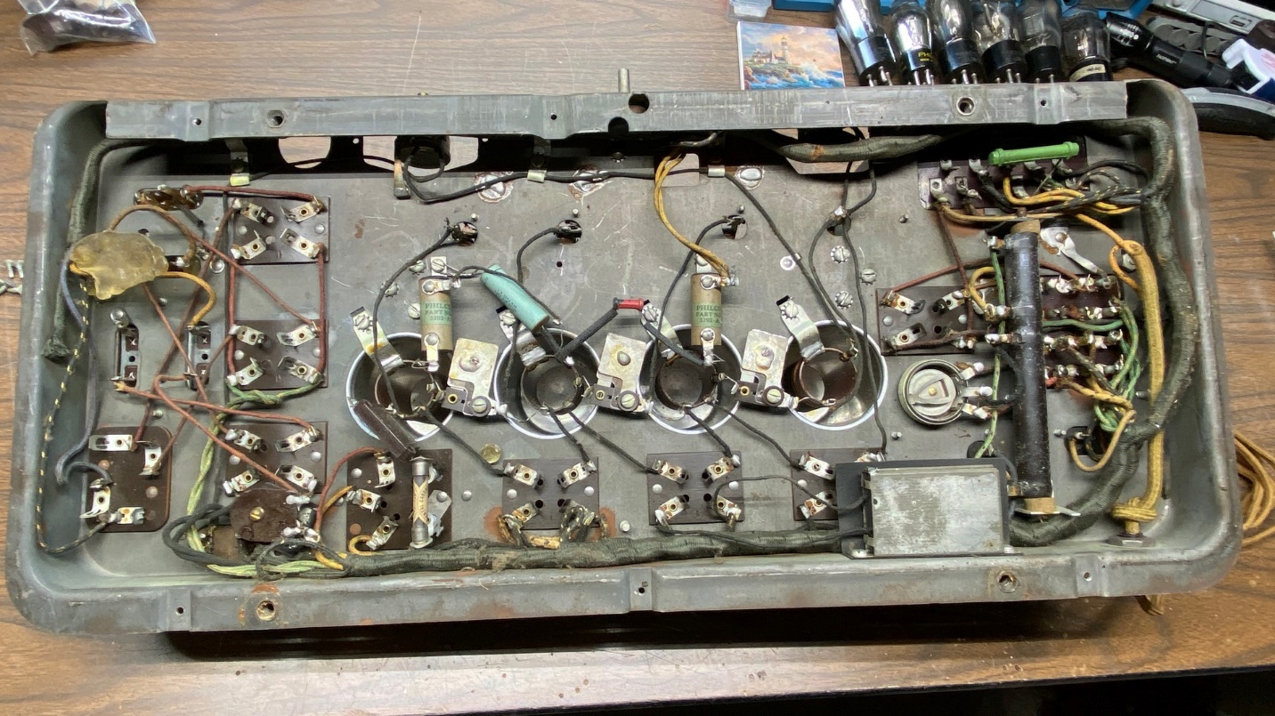
Looking under the chassis of the Philco 87, with bottom cover removed.
The radio can be repaired and returned to working condition, but the three-section resistor might be a challenge only in figuring out a way to replace the long cylindrical tube. I do not want to merely attach a resistor across the open section – that “open” section might decide to suddenly have continuity on an intermittent basis and cause the radio to not work properly. I am not worried about the audio interstage transformers. Those can be replaced, or there are workarounds for them which I will discuss at a later time.
This should be an interesting restoration. Stay tuned for more on this subject.