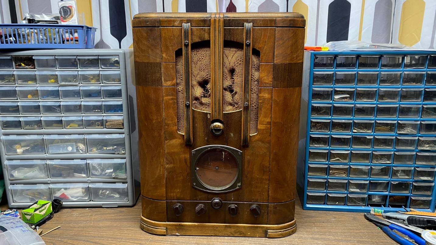
In the spring of 2022, I spotted what appeared to be a rough but restorable RCA model T9-10 tombstone radio on eBay. The radio was located at an antique mall in north Georgia and was listed as “pickup only.”
My stepdaughter and her husband live in northwest Georgia, so I asked them if they could pick this radio up for me. They agreed, so I hit the ‘Buy It Now” button on eBay and paid for the radio.
Debbie drove down there for a visit, and brought the radio back with her.
The radio sat on a shelf for several months until I decided to pull it out and see if indeed it could be restored.
Four of the set’s five knobs could be pulled off, although three of them required wrapping some crochet nylon around the shafts behind the knob and then pulling.
The fifth knob, the tuning knob, was held in place with a set screw – and the set screw would not budge.
I carefully sprayed a little PB Blaster on the set screw and let it soak overnight.
The next day, I was disappointed to find that the set screw still would not budge.
I had no choice at this point but to get rough.
I placed something under the tuning knob for support. Then, using a punch and a hammer, I struck the set screw a few times.
That was all that was needed – the set screw then loosened easily and the knob came right off.
I then pulled the chassis from the cabinet and looked it over.
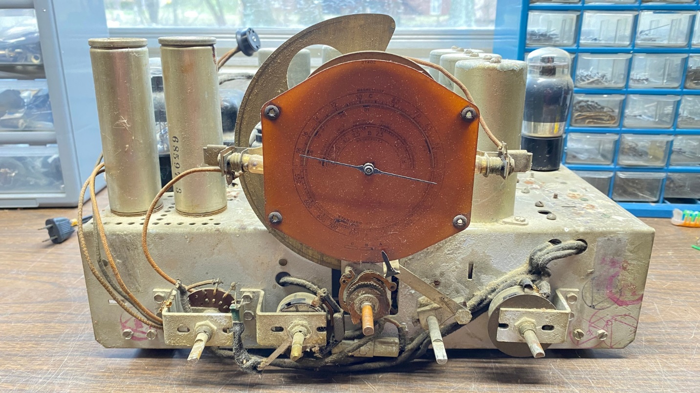
The RCA T9-10 chassis.
The T9-10 is a nine tube radio with a 6K7 RF amplifier, a 6L7 converter, a 6J7 oscillator, a single stage of IF amplification using a 6K7, a 6H6 double diode detector, a 6F5 triode audio amplifier, and a 6F6 pentode audio output tube. A 5Z4 was originally used as a high voltage rectifier.
You can see a copy of the schematic here.
The chassis of the T9-10 is very similar to the T8-14 but uses an additional 6E5 tuning eye tube. I used to own a T8-14; you can read about its restoration on the Philco Phorum.
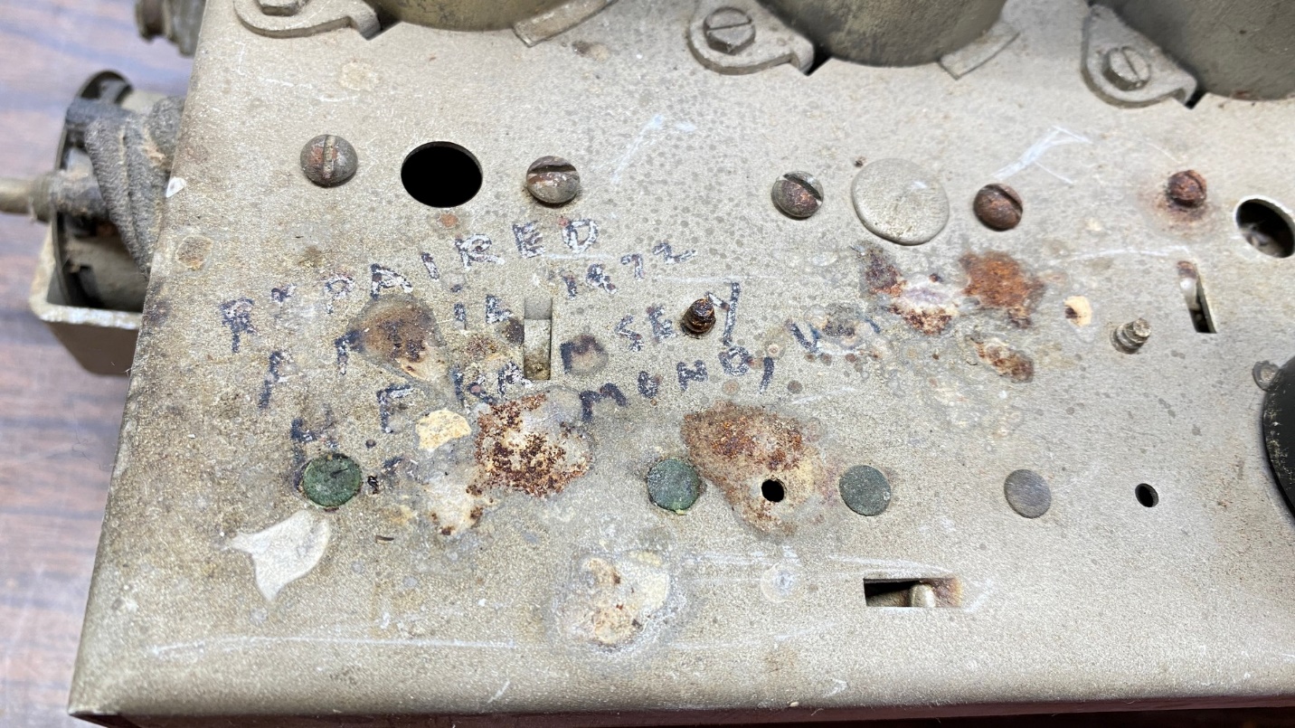
The person who was apparently the last one to work on this radio wrote his name and the date on top of the chassis.
The chassis had the typical dust and dirt from age and possible visits from rodents. I was surprised to find that someone had written on top of the chassis: “REPAIRED APRIL 1972” with their name, city, and state.
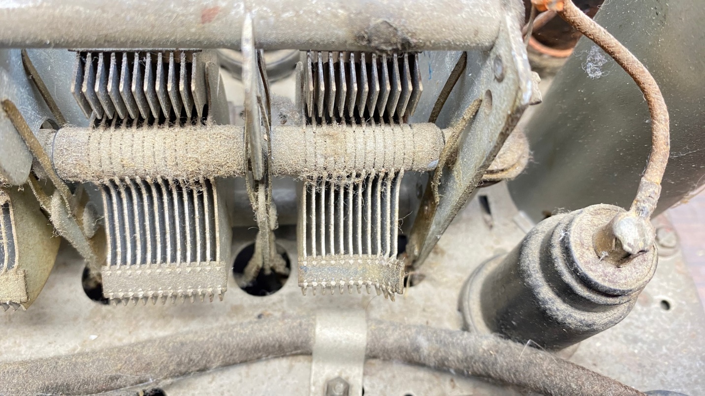
Damaged tuning condenser.
I noticed that one section of the tuning condenser had suffered damage. I was not sure if I would be able to repair that damage or not. I made a mental note to keep an eye out for a spare T8-14 or T9-10 chassis in case the damage was not repairable.
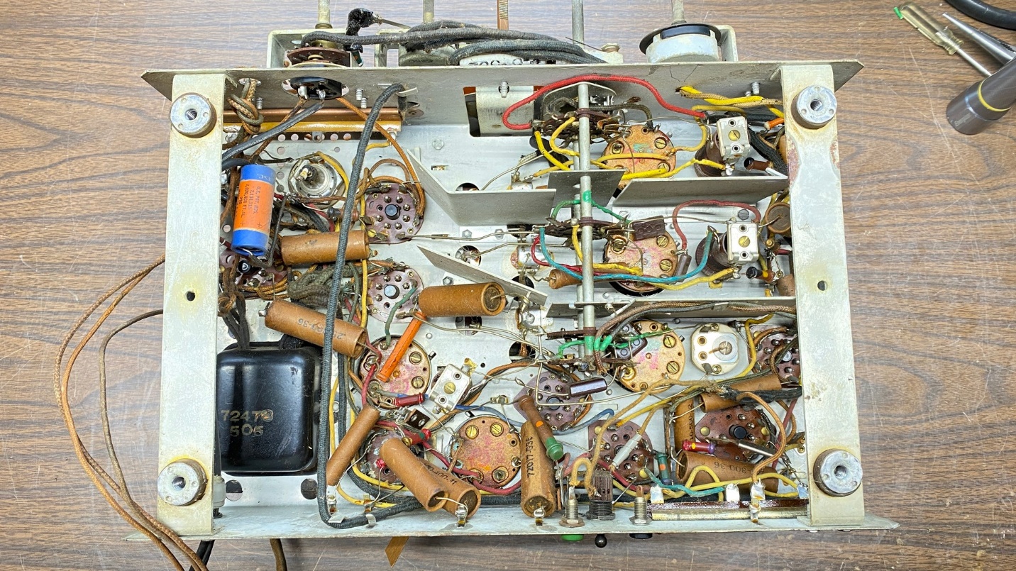
Looking under the T9-10 chassis.
I flipped the chassis over and looked underneath. It appeared to retain all of its original paper capacitors. The electrolytic capacitors had been bypassed with smaller, tubular units, and that appeared to have been done in the 1940s or 1950s. Fortunately, that person left the original electrolytic cans in place, with the positive terminals in place. This will make it possible for me to restuff the original cans with new components.
This chassis has two Candohm resistors. One, a dual 7500 and 9200 ohm unit, is open. The other one, a three section unit with resistances of 148, 32, and 85 ohms is still good! The resistances are not exactly the same as called for on the schematic but are well within acceptable range.
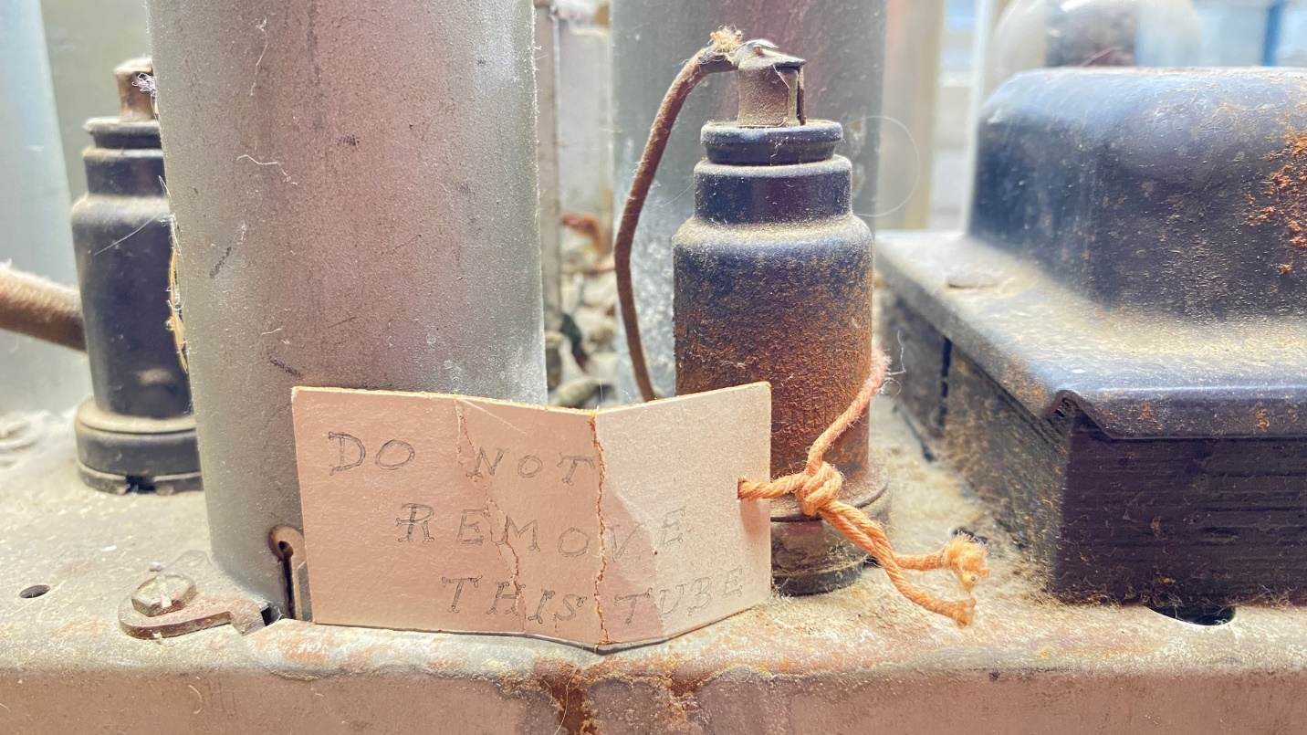
A strange tag attached to the 6K7 IF tube.
When looking over the top of the chassis, I had seen an odd warning tag tied around the 6K7 IF amplifier tube. The tag read “DO NOT REMOVE THIS TUBE.”
Looking carefully at the bottom of that tube socket, I soon found why that tube had the tag.
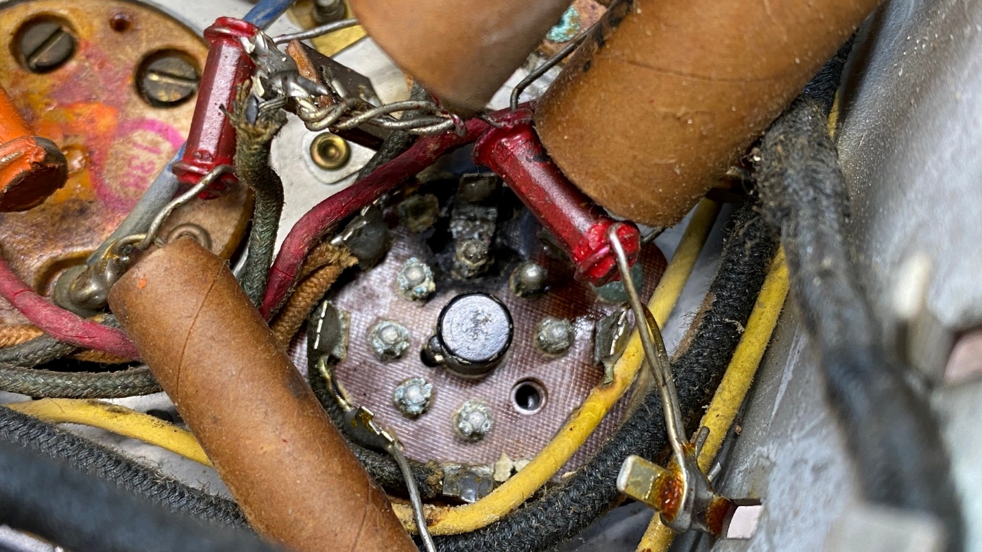
A damaged 6K7 IF tube socket.
The phenolic of that particular tube socket was burned away at pin 3, which is the plate terminal of the 6K7 tube. It was evident that someone, most likely the person who “repaired” the set in 1972, placed the contact of that pin over the pin so the radio would work.
I will repair this correctly by replacing the socket.
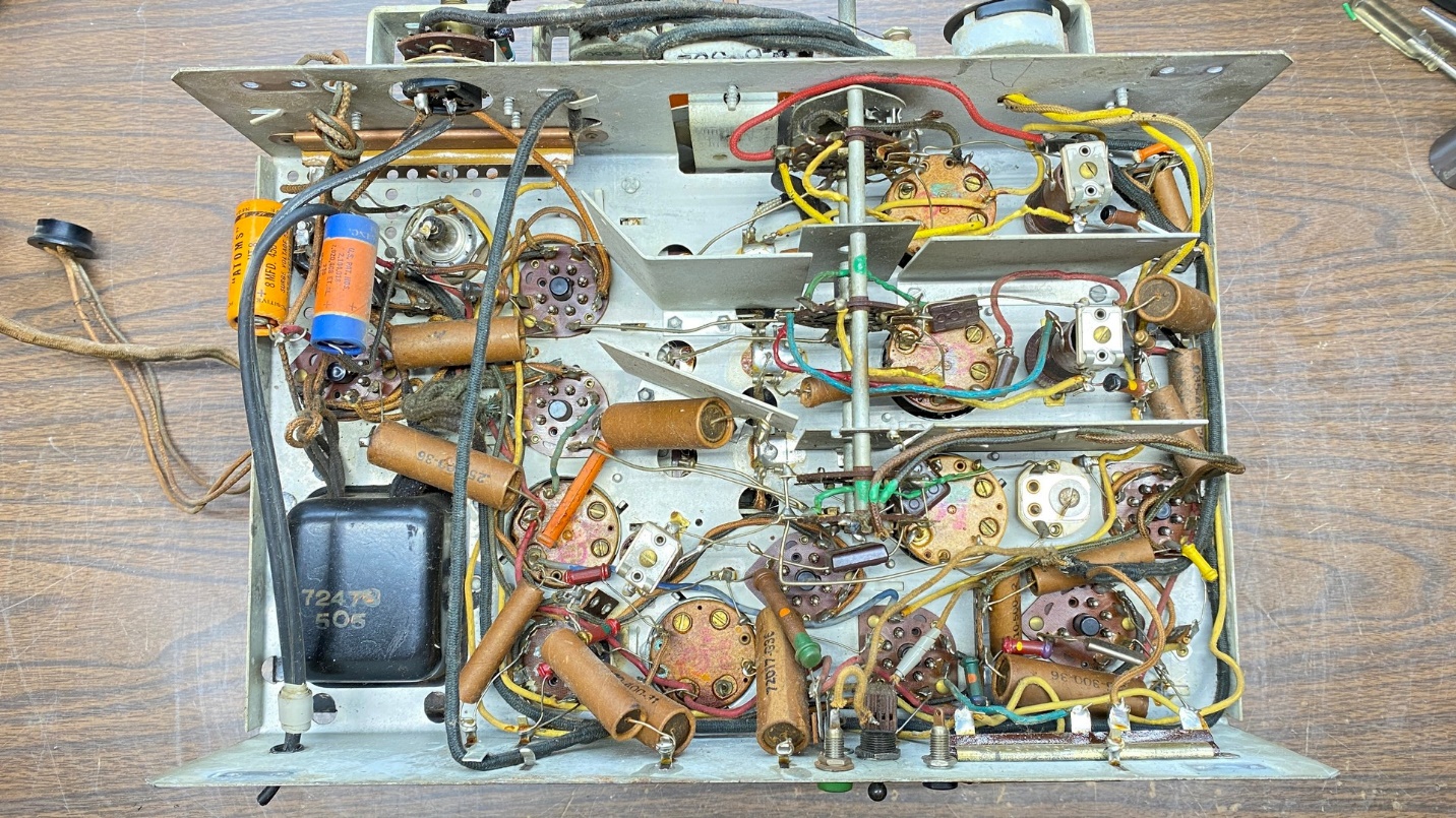
The T9-10 chassis is now ready for repairs.
I removed the chassis cross braces to give myself maximum access to everything underneath this chassis.
I should mention that I noticed one other odd thing about this chassis…
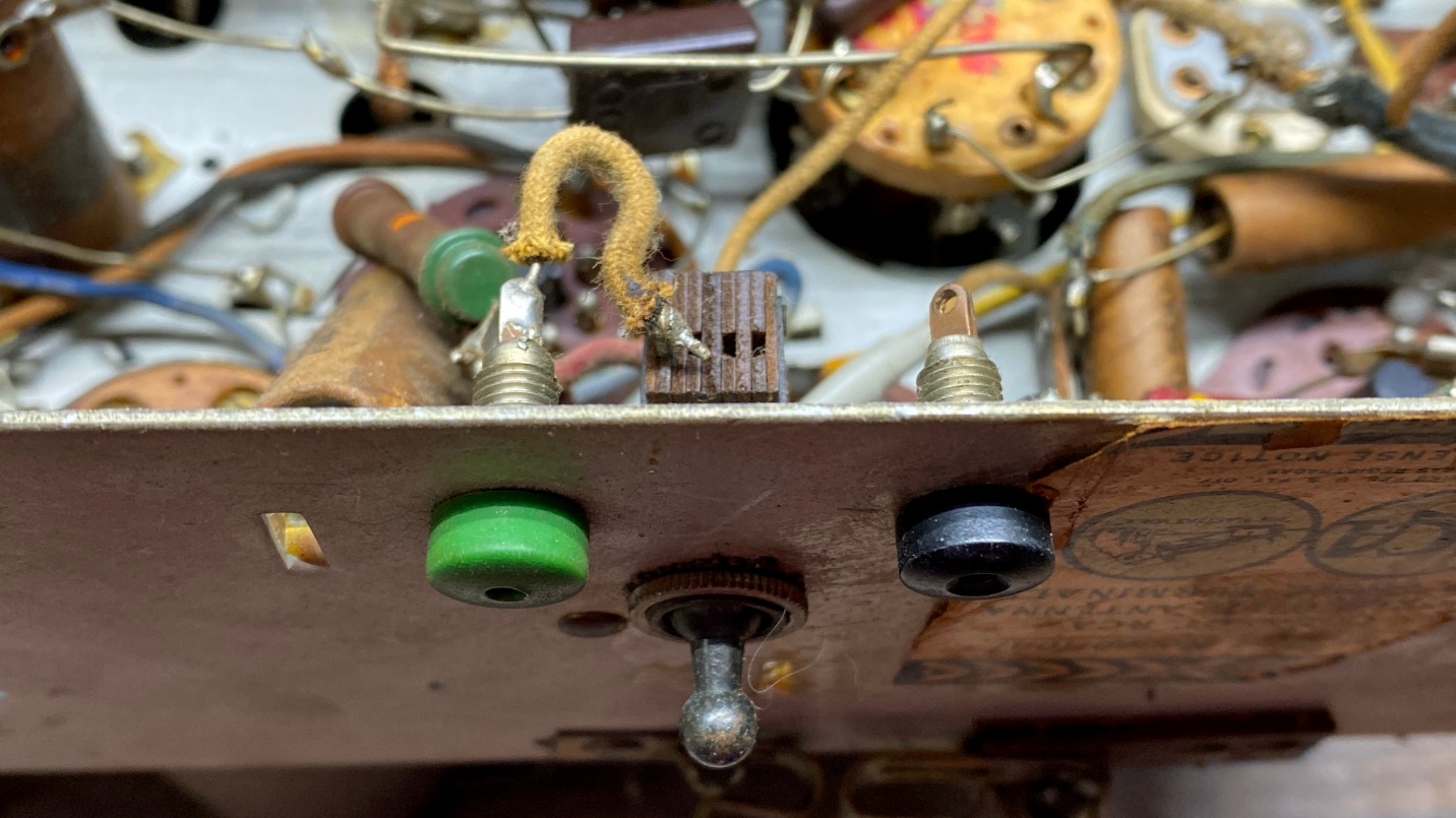
What appears to be a radio-phono switch and photo terminals have been added to the back of this chassis.
Someone added what looks like a radio-phono switch to the back of the chassis, along with two pin jacks. I will be removing these parts and will attempt to fill the holes with solder.
I am out of space for now, so I will return soon with more about the RCA T9-10’s restoration. Please join me then.