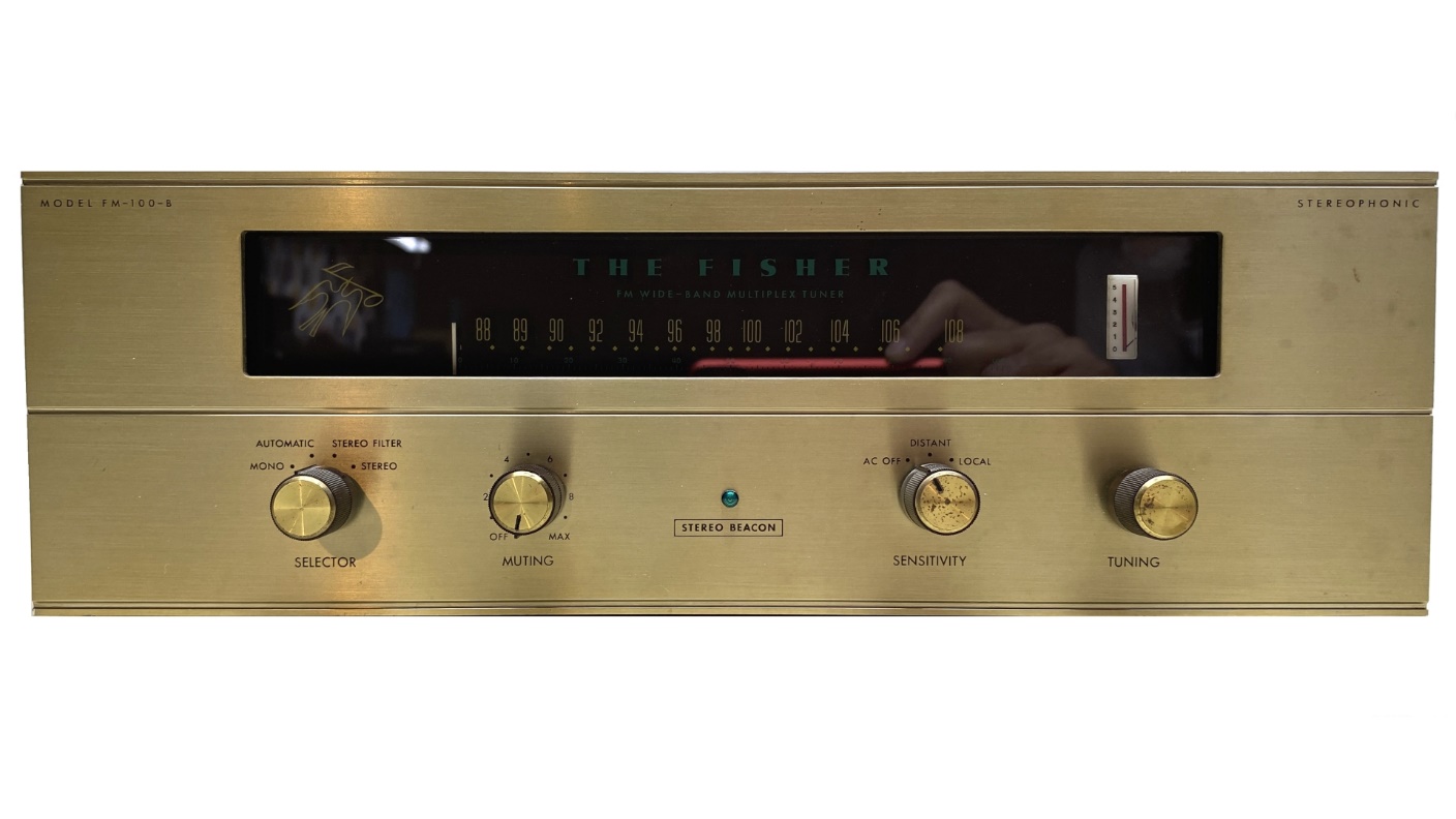
A few months ago, I spotted this Fisher FM-100-B tuner on the auction site, also known as eBay. Remembering how AudioKarma resident Fisher expert Dave Gillespie had described this tuner as “Fisher’s best bang for the FM buck [1],” I was intrigued and placed the tuner on my watch list.
eBay sellers know when people are watching their auctions and allow sellers to send watchers offers on fixed-price items. So, when the seller (who turned out to be someone I was acquainted with) sent me an offer I felt I could not refuse for this tuner, I agreed to purchase it.
It arrived in fine shape from a nearly cross-country trip (California to Indiana). It was missing most of its tubes and tube shields, as well as all its knobs and the four bottom feet. But it was an early production FM-100-B with the brass-color anodized aluminum faceplate.
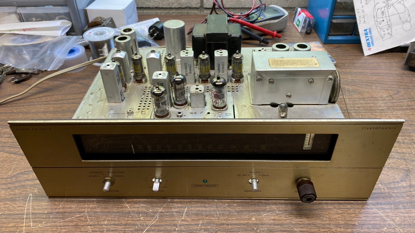
The Fisher FM-100-B as it looked after I acquired the tubes it needed, along with one of the missing knobs.
A reader of this blog offered to sell the missing seven-pin miniature tube shields to me, as well as NOS 6DJ8 and 6AQ8 tubes for the Golden Cascode tuner section, at a very reasonable price. I was happy to take him up on his kind offer. I found one of the missing knobs on the auction site and purchased it. I had the other missing tubes in my inventory.
Now, with everything I needed to make this tuner complete enough to be operable once it was restored, I decided it was time to proceed.
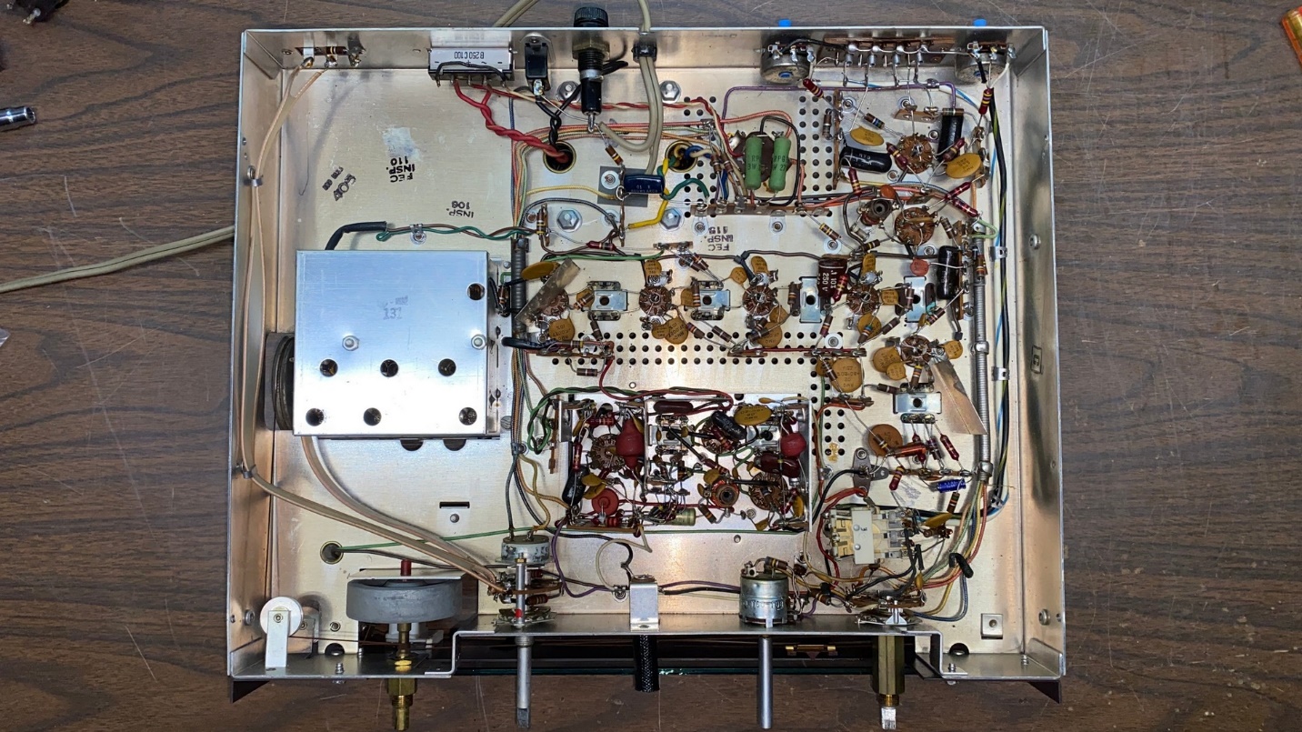
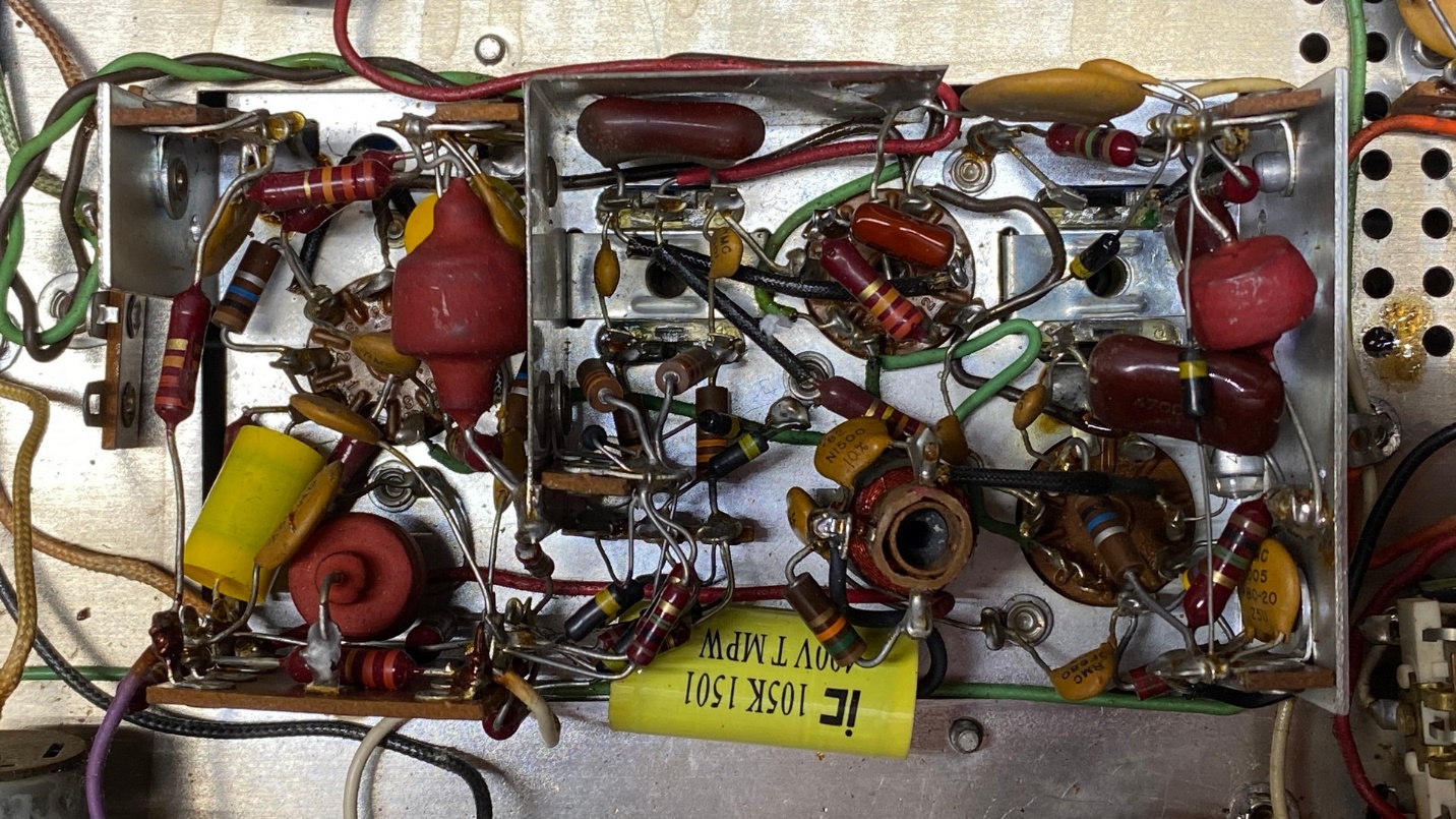
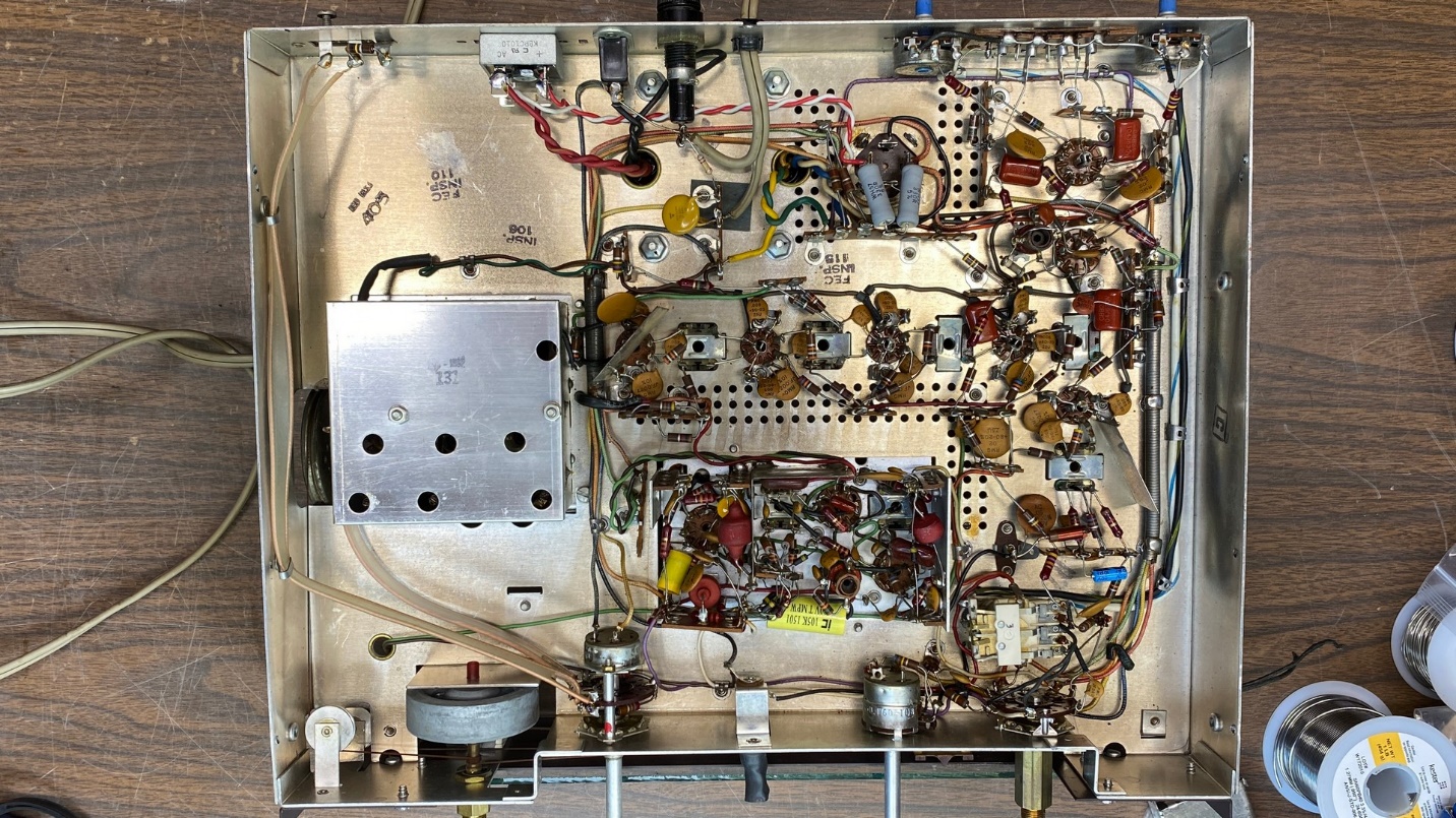
Under-chassis view of the FM-100-B.
I only have a copy of a Fisher service manual for Model FM-100-B, serial number 40001-49999, which I found here. The serial number of my FM-100-B is 348xx so I hoped I would not need that service manual for any serious troubleshooting.
Looking over the chassis from the bottom side of the tuner, it appeared that it had only received minimal service over the decades. Only two capacitors had been replaced – the AC line bypass capacitor and the small 8 uF electrolytic in the ratio detector circuit. Everything else looked original and untouched.
I chose my starting point this time as the AC line bypass capacitor.
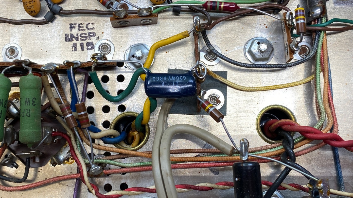
The AC line bypass capacitor had been replaced in the past.
Before long, I had replaced it with a new .01 uF X1/Y2 safety capacitor. These are designed to fail open which is desirable in this application.
The new AC line bypass capacitor – an X1/Y2 safety capacitor designed for the purpose.
The tuner had four 0.1 uF “dog turd” capacitors which needed to be replaced. Two of these were in the audio preamp circuit while two others were elsewhere in the tuner. I usually replace these with 0.1 uF metalized polypropylene capacitors, as their physical appearance is somewhat similar to the originals.
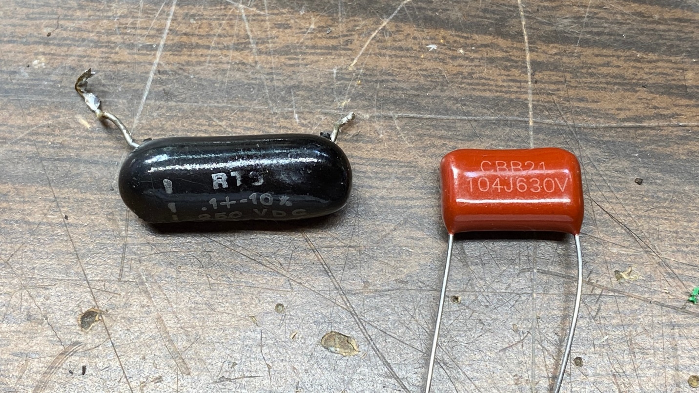
1962 “dog turd” plastic capacitor (left) and its modern replacement, a metalized polypropylene capacitor.
After some unsoldering, removal of the old components and installation of the new, I had two new capacitors in place of the “dog turds” in the audio circuit.
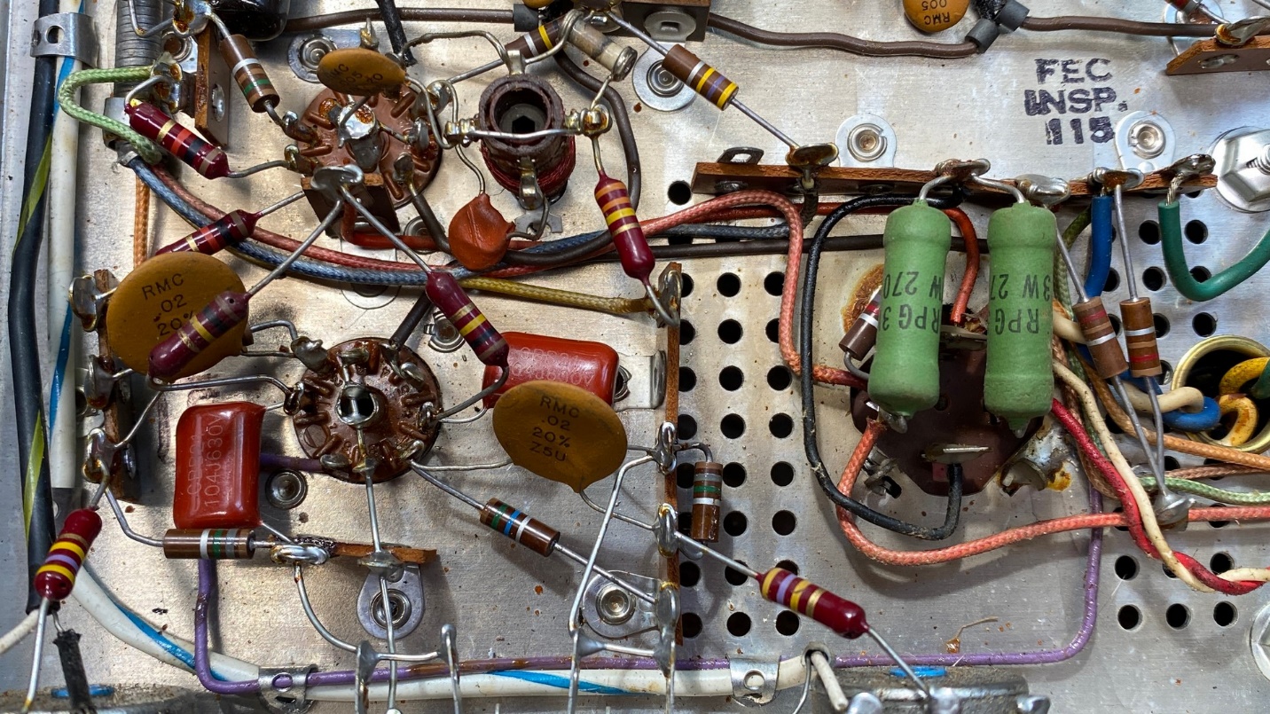
Both “dog turd” capacitors in the audio circuit have now been replaced.
Two other 0.1 uF “dog turds” were replaced in a similar fashion.
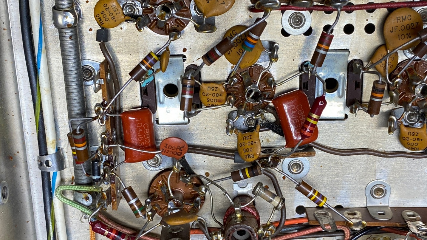
Two other 0.1 uF capacitors in the IF section were also replaced.
There is a diode, SR2 on the Fisher schematic, in the Muting circuit. It is barely visible, just below and to the right of the 82K resistor on the left side of the photo above. I checked it before and after I replaced the 0.1 uF “dog turd” capacitor which is connected to its anode. It passed both tests, so it was left in place.
Even though the 8 uF electrolytic in the ratio detector circuit looked like a recent replacement, I went ahead and replaced it again. This way I knew that all electrolytic and film capacitors in the tuner would all be new.
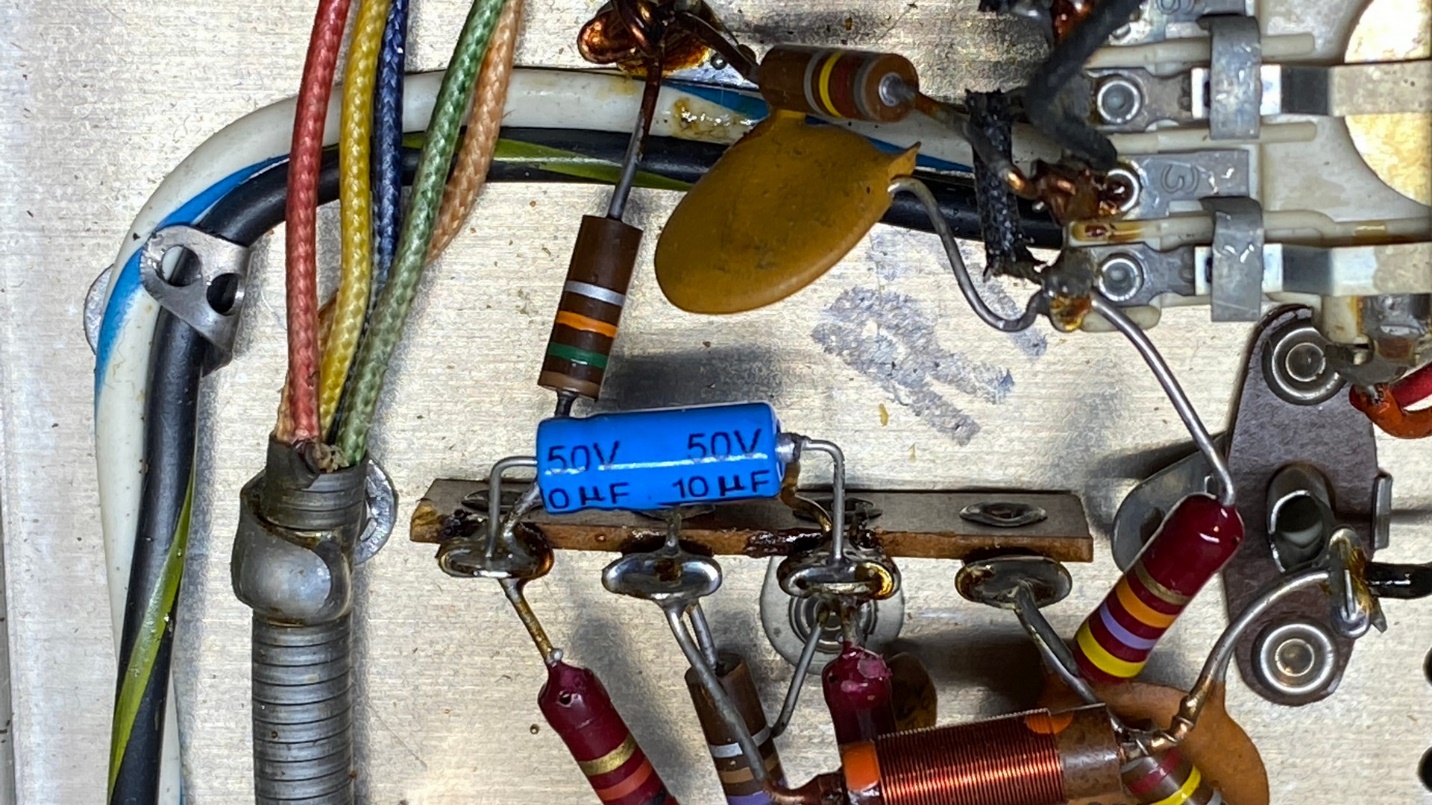
New 10 uF, 50V electrolytic in the ratio detector circuit.
There were three more “dog turd” capacitors within the multiplex decoder – one 0.0047 uF and two 0.047 uF – which I wanted to replace. The parts in a Fisher multiplex decoder are jammed into a very small space, which does not help. And I was out of .047 uF metalized polypropylene “Chiclet” capacitors, so I had to use yellow metalized film capacitors which are larger. After some careful work, though, I was able to successfully replace these.
New capacitors in the multiplex decoder.
I also replaced the 1 uF, 350V electrolytic within the multiplex decoder with a 1 uF, 400V metalized film capacitor.
Once I had completed replacement of old plastic-encased paper capacitors and two electrolytics, I turned my attention to the bridge rectifier. As is usually the case with vintage Fisher tuners, the original Siemens bridge rectifier was still in place. The old bridge rectifier is selenium and could fail at any time.
I replaced these with a large 1000 PIV, 10 amp silicon bridge rectifier. The 10 amp rating is far more than what is needed, but I find the terminals very handy for reconnecting the wires.
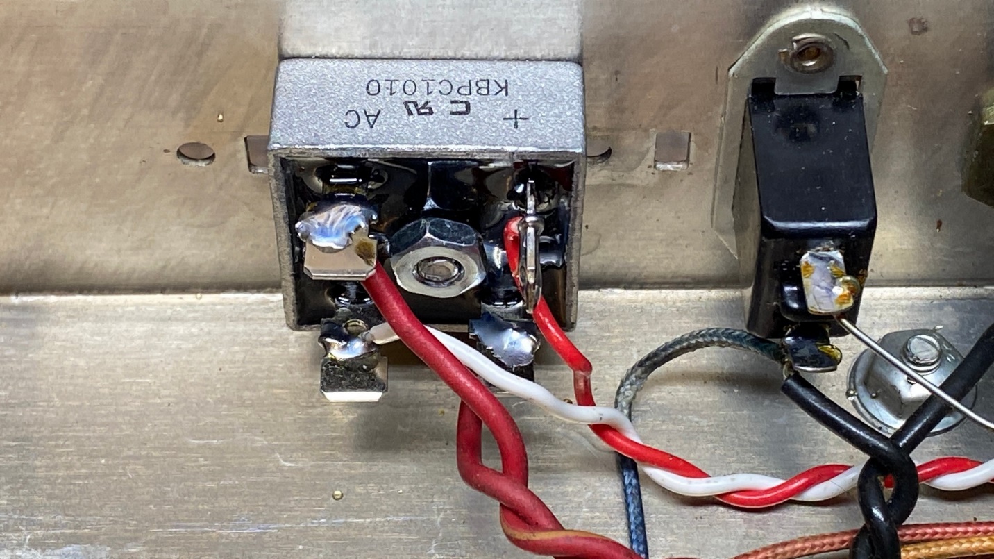
I replaced the original Siemens selenium bridge rectifier with a new silicon bridge rectifier.
I had one more item to address under the chassis, and that was the four-section twist-lock electrolytic capacitor. It contained four 40 uF capacitors. I chose to restuff it by carefully removing it from the chassis and cutting off the lower “lip” so that I could remove its internal components.
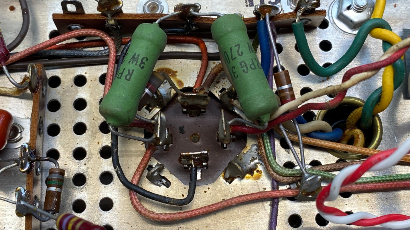
The main filter (four section electrolytic) capacitor and associated power resistors before replacement.
This particular capacitor did not want to come apart, however. I ended up having to “cook” it in my toaster oven before I could pull the internal components out of the outer can.
Once I finally had it open, I installed four United Chemicon 47 uF, 400V “pencil” electrolytics rated at 105 degrees C. I have shown how I restuff these electrolytic cans in previous restoration articles and chose not to show it here for that reason.
This time, instead of retwisting the lugs once I had the can back on the chassis, I soldered the twist-lock lugs to the chassis so if it must be removed again, it will be a simple matter of unsoldering the lugs and pulling the can out.
Since I had replaced the selenium bridge rectifier with a silicon unit, I needed to add resistance to compensate for the lower voltage drop of the silicon rectifier. I chose to do this by replacing the two 270 ohm, 3 watt power resistors in the power supply with two 330 ohm resistors as shown below. This adds 120 ohms of resistance which will compensate for the higher B+ produced by the new bridge rectifier.
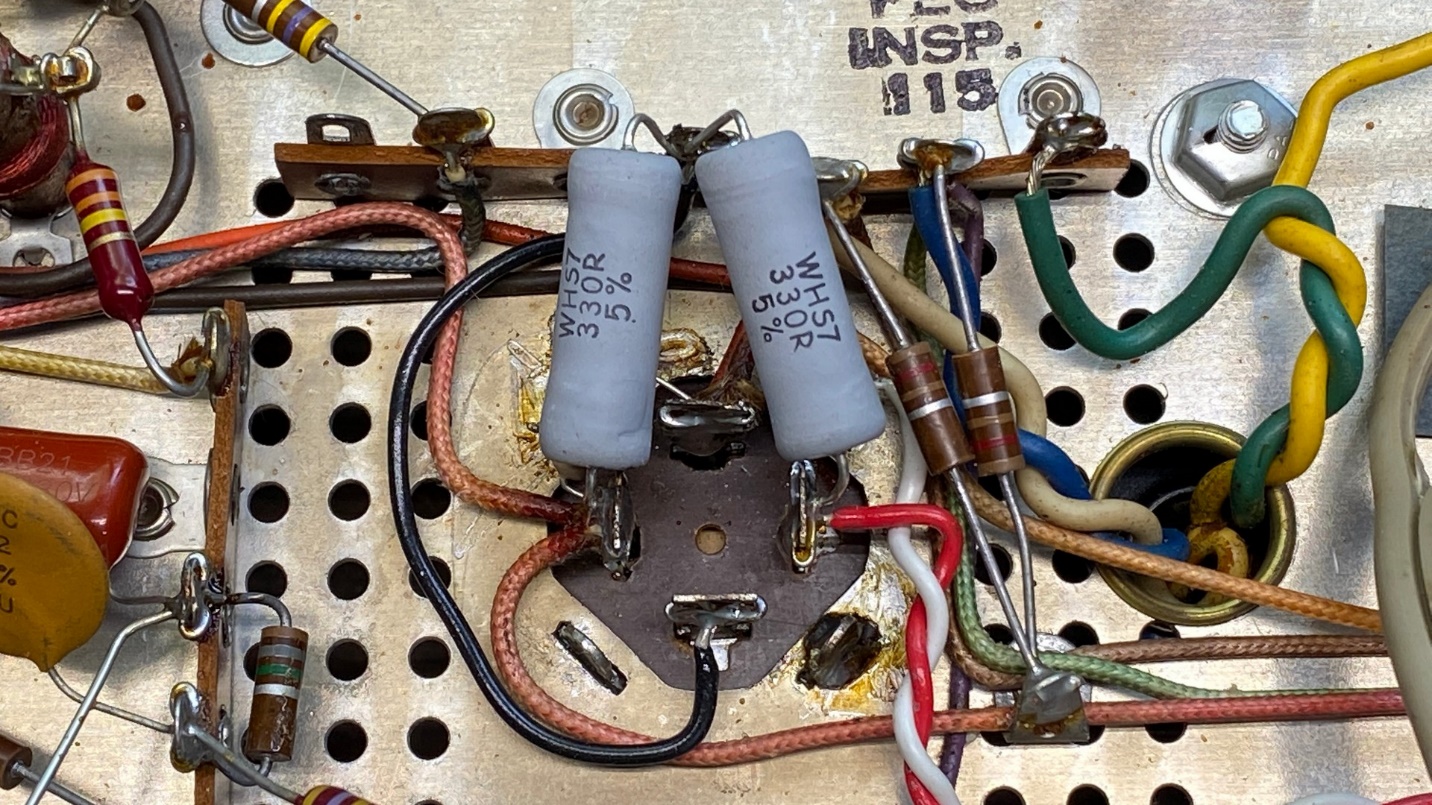
How things looked after the main filter capacitor had been removed, opened, restuffed and reinstalled. New power resistors were also installed.
At this point, I had replaced everything under the chassis which I felt needed to be replaced, and it looked as shown below.
How the chassis looked underneath after replacement of components.
Now it was time to try out the tuner. I connected it to my workbench Lepai solid-state amplifier, added a temporary antenna, plugged the tuner in, and turned it on.
Nothing.
I unplugged the tuner and double-checked the fuse. It was ok. But the tuner would not turn on.
I then checked the power switch. Aha! When the switch was turned on, a check with my multimeter indicated the switch was still “open”, i.e. not making proper contact.
So, I gave the switch a shot of DeoxIT and then turned it on and off about 40 times to work the DeoxIT into the contacts of the switch. After I did this, I checked the switch with my multimeter again. This time, with the multimeter set to resistance as before, when the switch was turned on the contacts indicated “closed” on the meter as they should have.
I then hooked the tuner back up, plugged it in, and turned it on. Now the tuner came on; the Stereo Beacon lamp and the lamp behind the tuning meter both came on. The Stereo Beacon lamp went out as the tuner warmed up. Soon, I could hear the familiar hiss of FM noise in my workbench speakers.
I was able to tune in several FM stations. FM Stereo was working. When a strong enough signal was tuned in, the relay clicked, and the Stereo Beacon lamp illuminated.
I tried the Muting control and much to my surprise, it worked!
Problems noted: The dial lamps, two festoon bulbs on either side of the dial glass, were burned out. Tuning was very stiff, and the tuning knob was hard to turn. The tuner, while working, seemed to be in need of alignment. But it was working!
I had a couple warm white LED fuse lamps which had already been modified by me previously for the skinnier festoon end caps, so I carefully removed the end caps from the original festoon lamps and soldered them to the ends of my LED fuse lamps. These were then installed in the tuner. While I was at it, I went ahead and replaced the Stereo Beacon bulb with an LED bayonet lamp. I also replaced the lamp behind the tuning meter with an LED which had a bayonet base and its emitter connected to the base with flexible leads, to better illuminate the tuning meter.
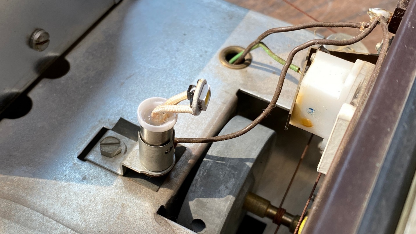
LED lamp with flexible leads placed behind the tuning meter.
With the bulbs replaced, I decided to try and do something about the stiff tuning issue. I removed the shield from the tuning condenser and gave the tuning condenser shaft some lubricating oil. Then, noticing the bushing through which the tuning shaft passed, I removed the bushing, cleaned the tuning shaft, and then lubricated it with white lithium grease after which I reinstalled the bushing.
After doing all this, the tuning was much better. It still was not as smooth as I was accustomed to, but it was a definite improvement.
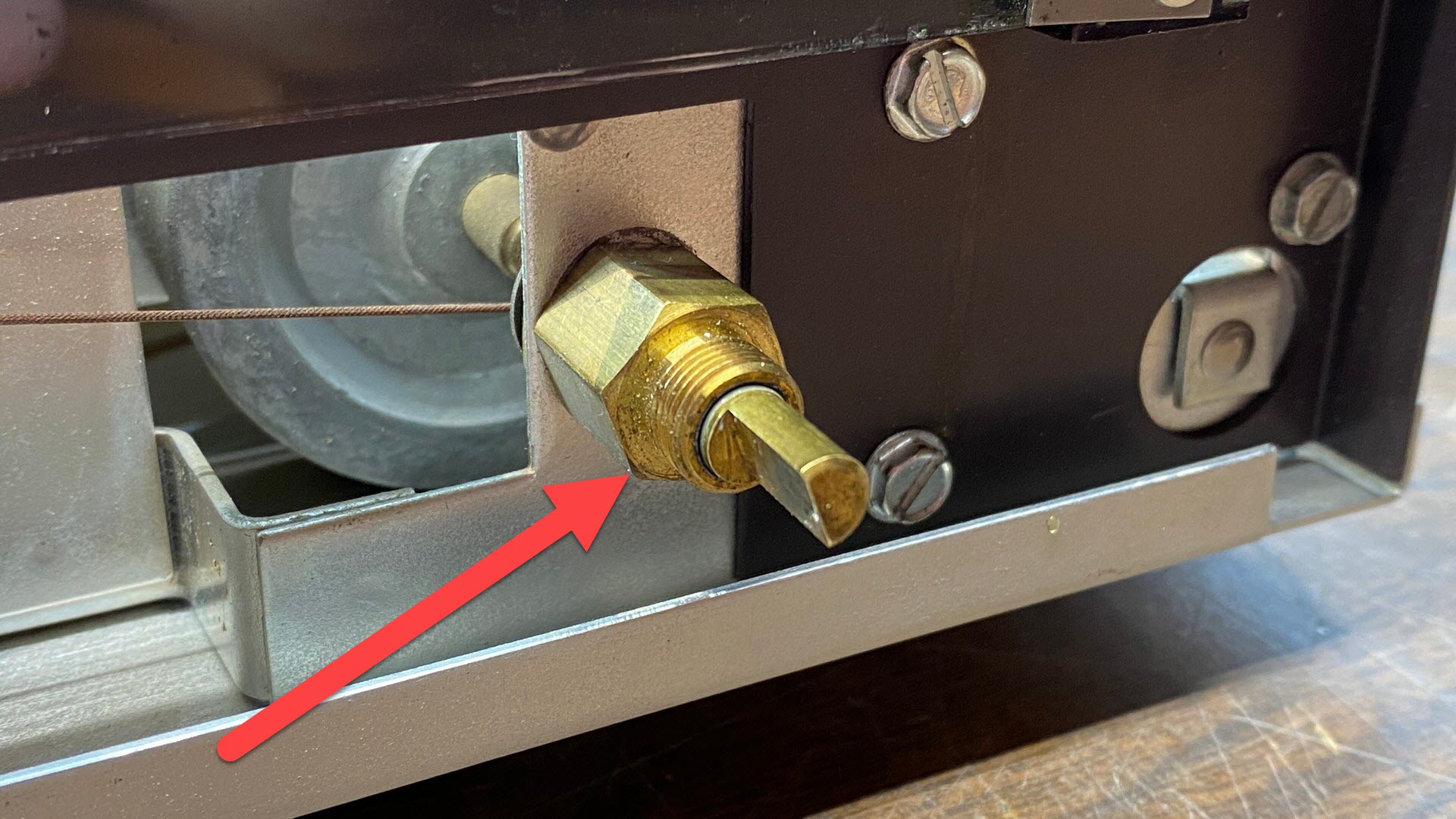
This bushing was removed, and the tuning shaft cleaned and coated with new white lithium grease. The bushing was then reattached.
Finally, it was time to give the tuner an alignment. First, I had to set the dial pointer at zero on the logging scale. With the removal of old glue on the back side of the pointer where the dial cord passed through, the pointer could then be set to zero as needed. Then, following the alignment procedure in the Fisher service manual, the IF alignment was straightforward and uneventful.
The RF alignment, however, ended up being multiple back and forth adjustments between 90 MHz and 106 MHz. As stations were being picked up even without an antenna, I could check my progress as I went along. After four or five repetitions, I had the tracking set as close as I felt it could be. For example, stations at 92.5, 96.1, and 104.7 MHz were coming in at approximately the correct positions on the dial.
Finally, I put the bottom cover and front panel back on the tuner and tried it out one more time. Take a look below.
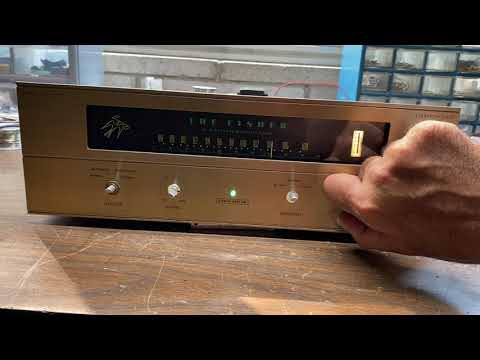
This was recorded with a poor temporary antenna. As you can see, even with this setup, the FM-100-B was pulling in several stations. With a better antenna, the tuner picked up even more signals, including the elusive WUOL at 90.5 MHz, which can normally only be received this far away from Louisville on car radios. Mind you, WUOL was weak, but identifiable.
So that concludes another successful Fisher tuner restoration. I will eventually find the other three knobs I need. That is not a concern. The same goes for the four plastic feet. I hope you enjoyed reading along.
[1] “FM-100B: Fisher’s Best Bang For The FM Buck”, https://audiokarma.org/forums/index.php?threads/fm-100b-fishers-best-bang-for-the-fm-buck.645489/Photo at top of page: A semi-formal portrait of The Fisher FM-100-B tuner, using knobs borrowed from another Fisher tuner. Only semi-formal due to the reflection of my hand and the edge of my iPhone in the dial glass, darn it!