Wrapping it all up.
My modified Philco model 54C was working, but it was only receiving the upper end of the AM band. I needed to do some investigating to find out why this was happening, and what I could do about it before I could proceed with applying the final touches to the radio.
I made an inquiry on the Philco Phorum to discover whether I was on the right path – that is, the trouble must be in the set’s oscillator circuit. A few kind people on there soon confirmed my suspicions were correct.
I then spent some time studying Philco radio schematics which were similar to model 54. I decided to focus on model 602, which is probably the closest in design to the 54 since the 602 replaced the 54 during the 1936 model year.
Almost right away, I noticed something about the 602’s oscillator coil. Its tuned winding measures 7.5 ohms; its feedback winding (though which B+ passes) is 2.4 ohms. On the 54 schematic, the tuned winding is shown as 4.6 ohms and the feedback winding as 9.3 ohms – exactly the opposite of the 604!
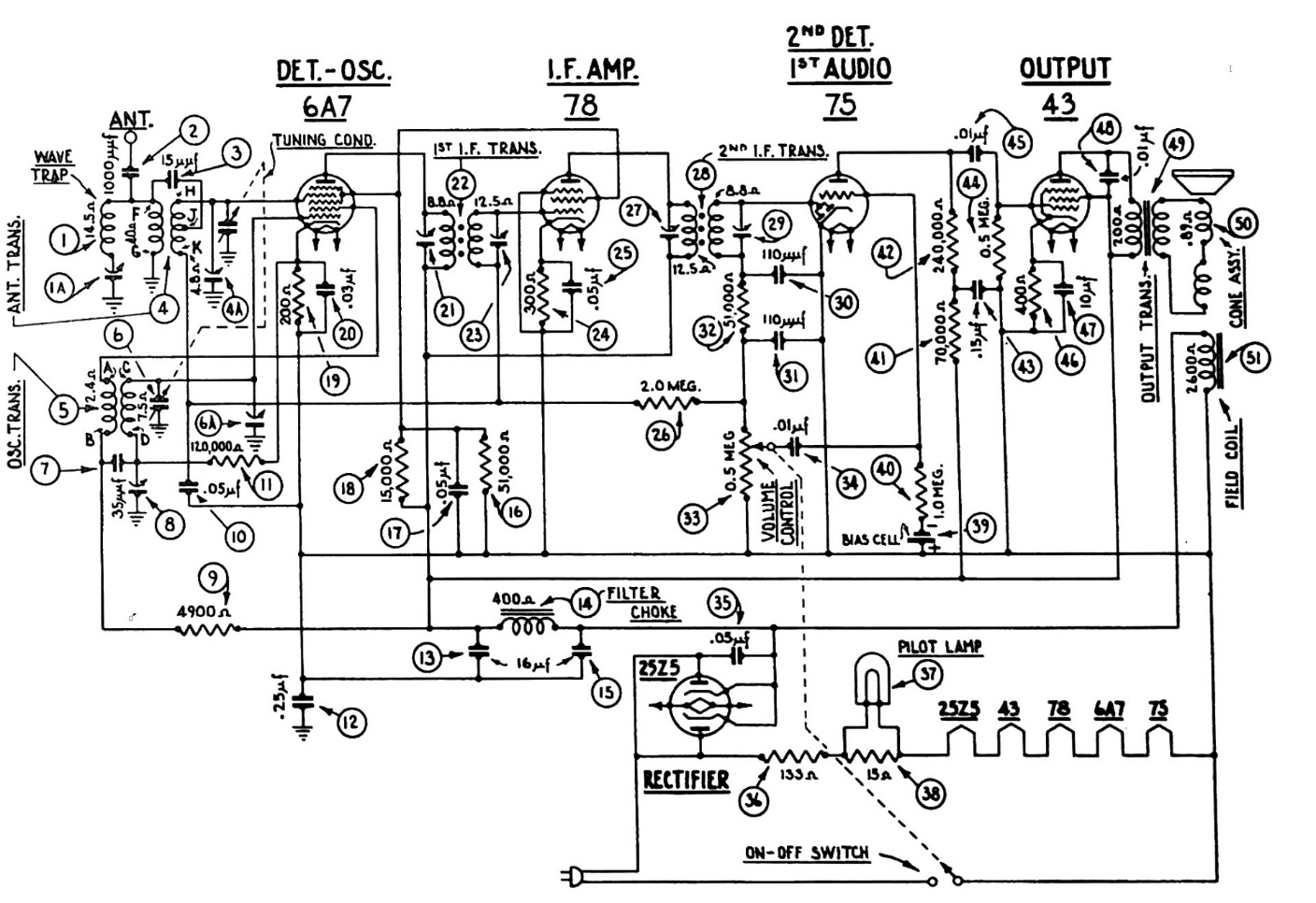
Philco model 602 schematic. Its oscillator coil is part (5). Click the schematic above or click here to see a larger version.
Obviously, one of these schematics was wrong. Since I had reconnected the oscillator coil so that the winding with the higher resistance was the feedback winding, and the radio was not working properly, it was likely the 54 schematic which was in error.
Compare the schematic above to what became the fifth revision of my modified 54 circuit, below.
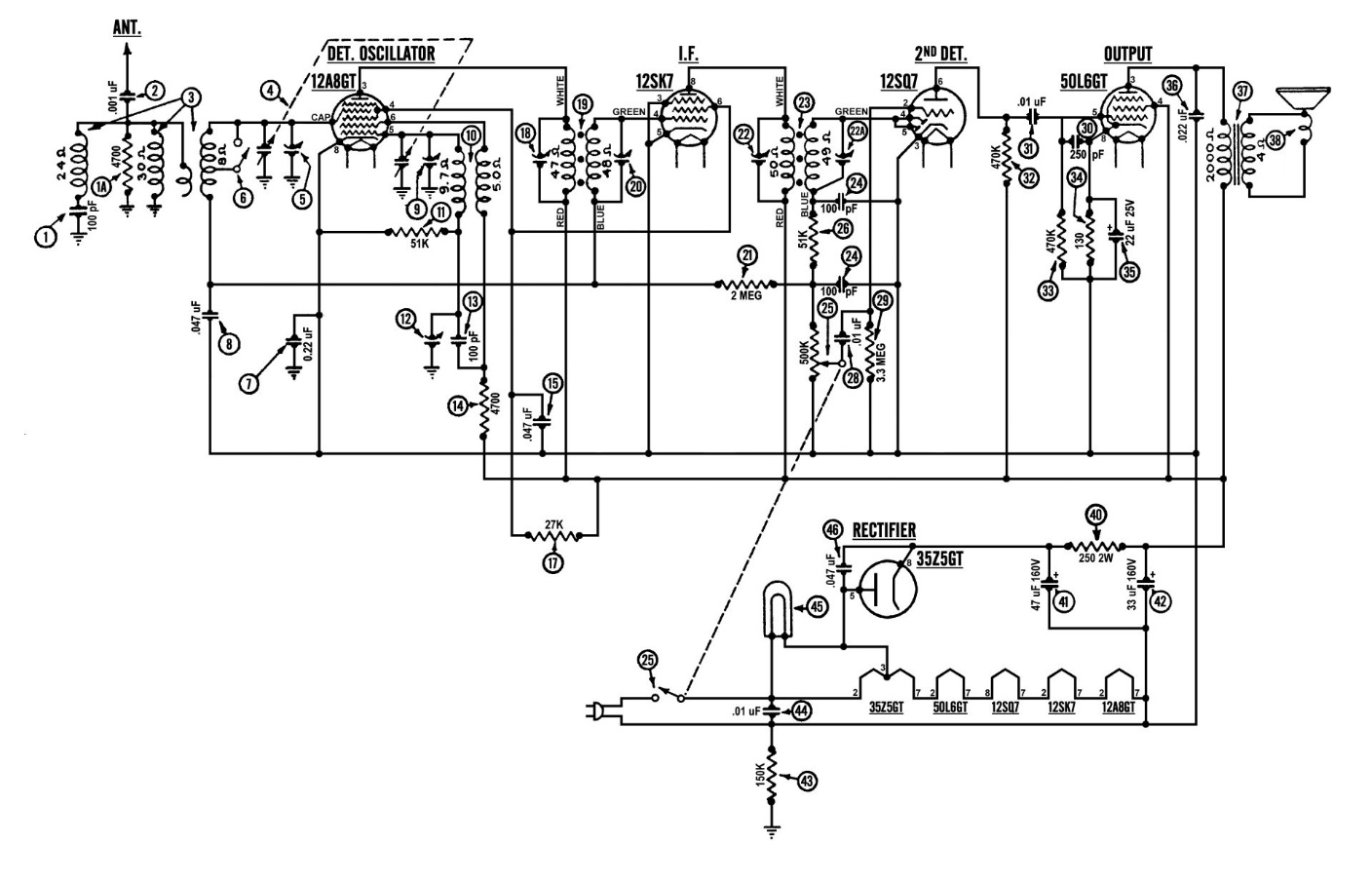
The fifth (and final) revision of my modified Philco 54 circuit. Click the schematic above or click here to see a larger version.
I removed the 54 oscillator coil and baked it in my old toaster oven for a half hour at 225 degrees Fahrenheit. After it cooled off, I put it back into the 54 chassis. Only this time, I connected the winding with the higher resistance as the tuned winding, and the other winding as the feedback winding.
I also changed the wiring of the low frequency padder, part (12) so it connects to chassis ground instead of B-. I had noticed this was done in other AC/DC radios, including the Philco 602. Removing the padder’s connection to B- makes the part safer, since B- in this radio is directly tied to the neutral side of the AC line. This was an important consideration since the low frequency padder is mounted at the upper left of the 54 chassis where it could be easily touched.
When I was finished, I reconnected my longwire to the antenna lead, plugged the radio chassis in, and turned it on.
Once the tubes warmed up, the radio began to work. And work it did! Now it was tuning the entire AM band as it should have.
I had already aligned the IF trimmers. Now that the radio seemed to be working properly, it was time to align the antenna and oscillator circuits.
I made a copy of the model 54 dial scale and printed it out to the proper size. I then cut this out and taped it to the chassis over the tuning shaft. I attached the dial pointer. There was no index line or dot, so I set the pointer as close to the 9 o’clock position on the tuning shaft as I could. I then attached the knobs and turned the radio on, also turning on my bench signal generator at the same time.
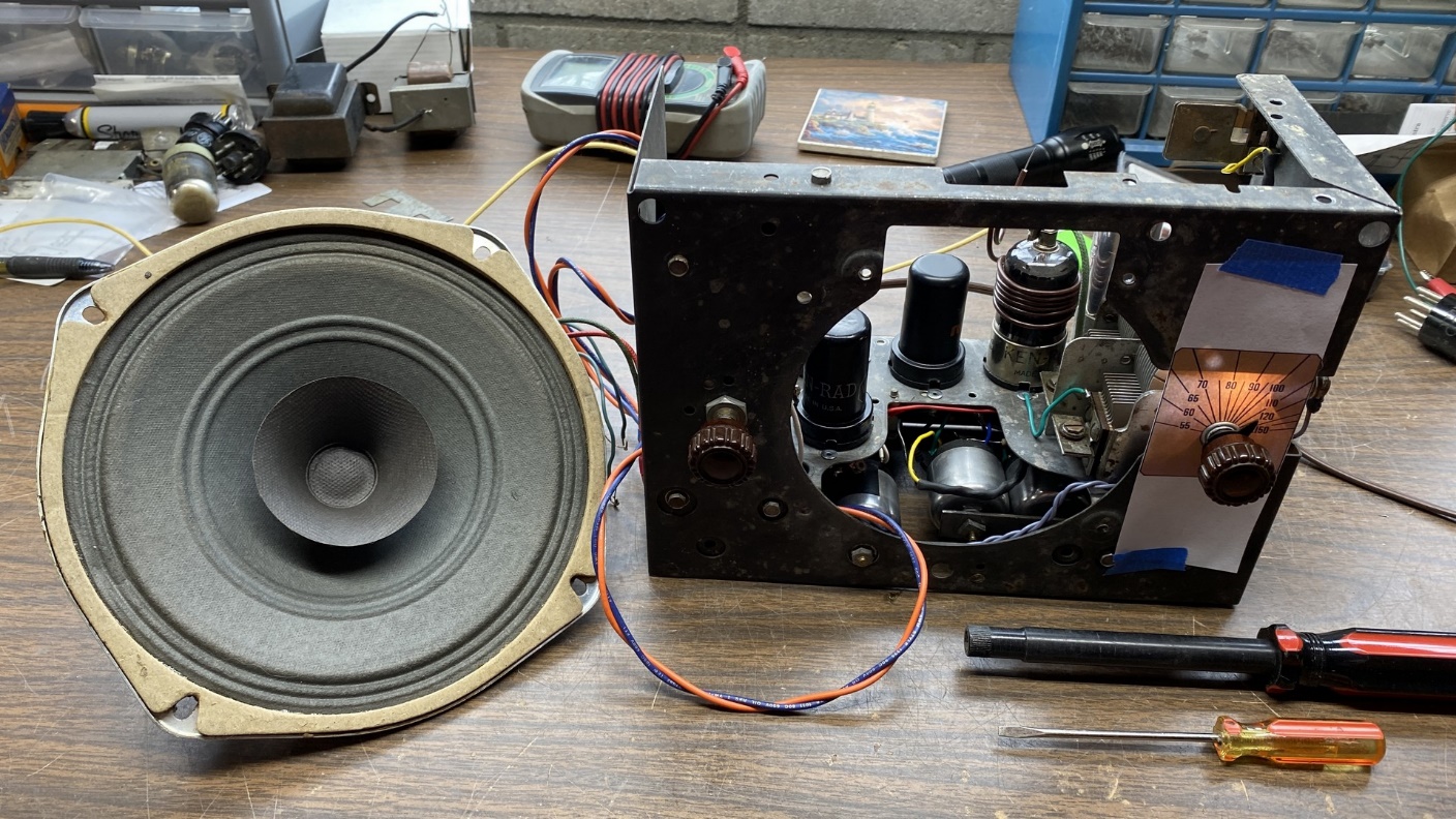
The 54 chassis, now working, is ready for an alignment.
The printed dial scale allowed me to achieve a fairly accurate alignment of the AM band.
Did you notice the special ¼ inch nut driver in the photo above? This is a non-metallic nut driver made just for adjusting the ¼ inch alignment nuts used in 1930s Philco radios. These are available from my friend Steve Davis, who also makes other tools for rebuilding Philco Bakelite block capacitors as well as making wood cabinet trim and complete cabinets. Visit his website for details.
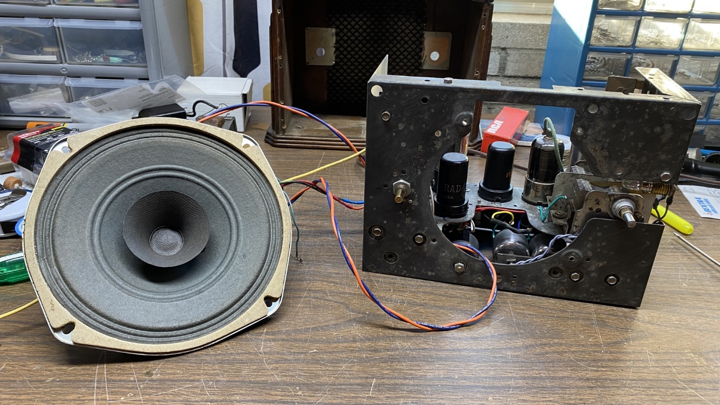
Now that I had the radio up and running, I turned my attention to the speaker issue.
After the ads I had placed on the two vintage radio forums I frequent failed to turn up a suitable speaker, I decided to look for something new. I found one on the Parts Express website which seemed to be just what I needed to complete this Philco 54C, and ordered it.
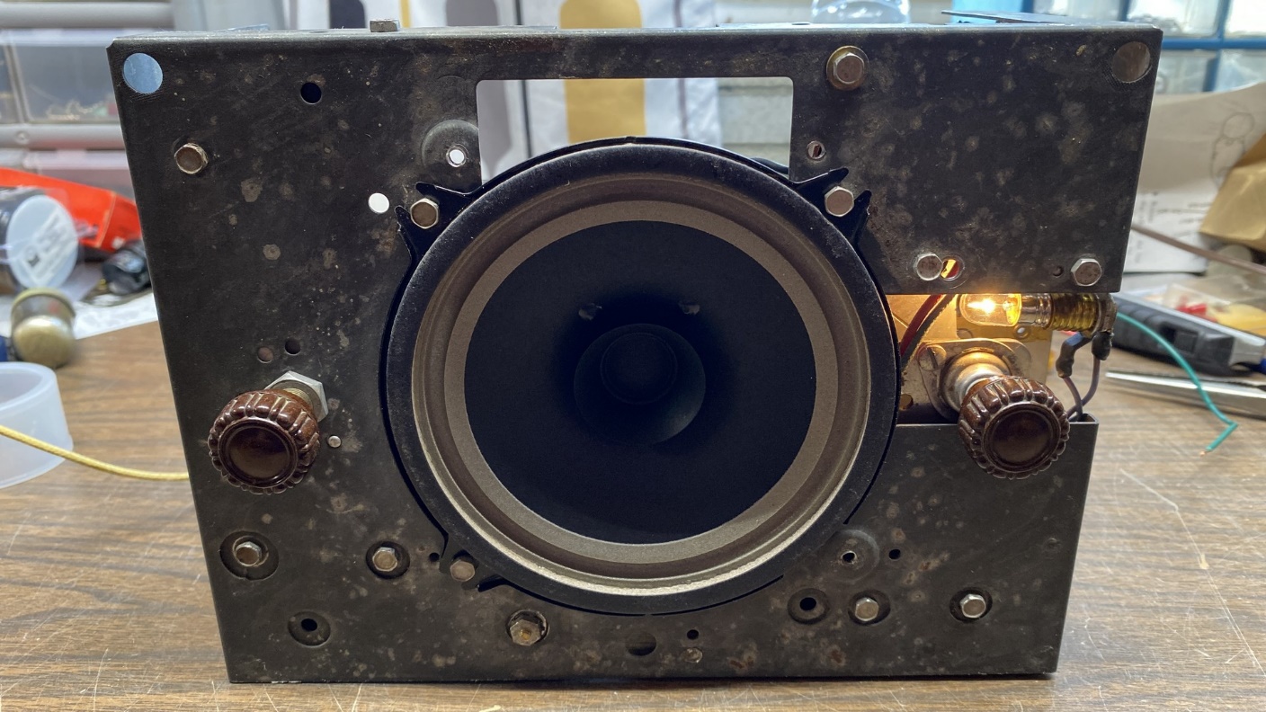
The Philco 54 with its new Visaton speaker.
The speaker, a Visaton FR13-4 full range speaker with a 4 ohm voice coil, was a 5 inch speaker with extended mounting tabs. It appeared to be a suitable replacement for the original Philco speaker.
As it happened, I ordered – and received – the last one Parts Express had in stock at the time. They have since received new stock of this speaker.
The speaker turned out to be a bit smaller than the original Philco speaker, so I had to drill new mounting holes in the chassis in order to install it.
I also needed an audio output transformer. I decided to use the Thordarson transformer I had been temporarily using with the test speaker, and installed it permanently in the 54 chassis where the filter choke had originally been mounted.
You may notice in the photo above that one of the four mounting tabs on the Visaton speaker is missing. I cut it off with my Ryobi “Dremel” tool because the chassis had a raised “bump” where the fourth tab would have been. This “bump” interfered with mounting the speaker flat against the chassis.
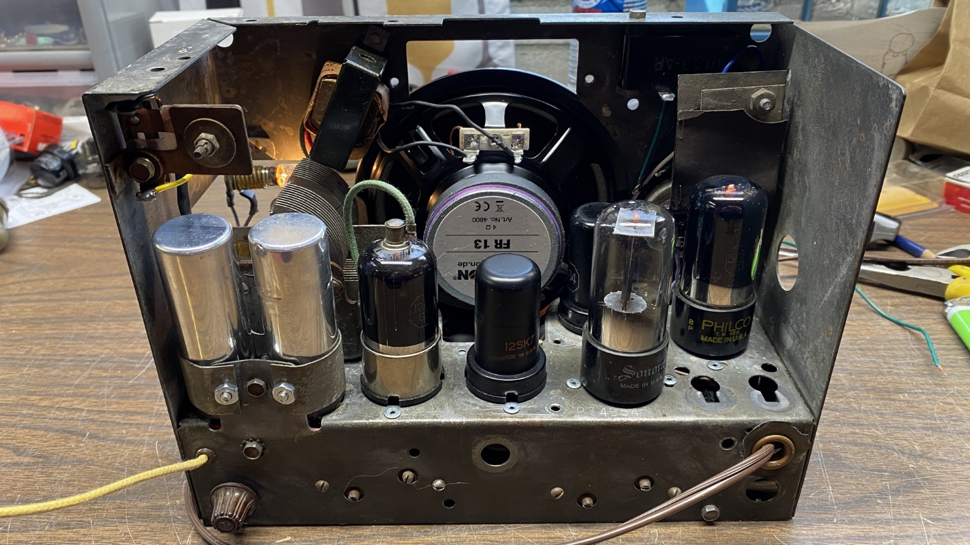
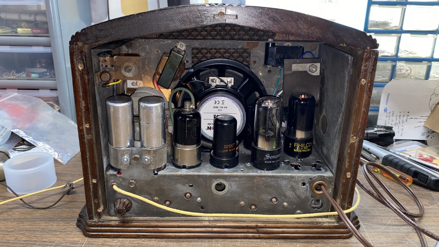
Rear view of the completed Philco 54 chassis.
That Visaton speaker has a very large magnet in back. That magnet is sitting only a small fraction of an inch from the 12SQ7 tube. However, when the radio is in operation, it does not seem to affect reception at all – nor did I expect it to, especially since the 12SQ7 metal shell is grounded to the chassis.
I would have preferred to have a speaker from an older AA5 radio, as I had mentioned in the previous installment of this series, mainly because an older speaker would have had a smaller magnet which would have provided better clearance. In addition, it likely would also have had provisions to mount the audio output transformer on its frame. However, this was the best I could do at the time.
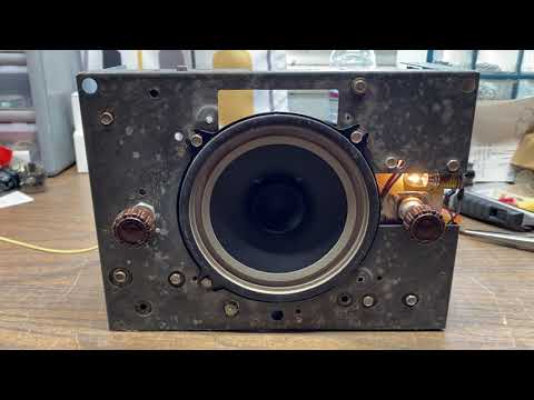
The radio plays well and sounds very good with that Visaton speaker, as you will notice in the short video below.
The modification of this Philco 54C has been a success. True, I did run into some issues along the way, but I achieved my goal of eliminating those large, bulky, power resistors.
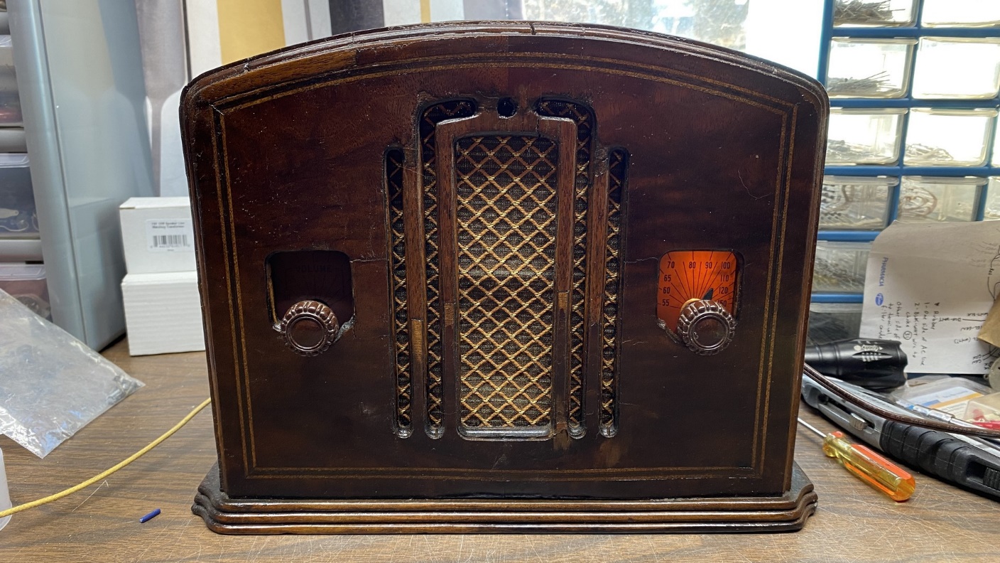
The completed Philco 54C back in its cabinet.
Final thoughts on this project
I would have been happier with the end result if I had been successful in finding the 5-1/4 inch pincushion speaker that I really wanted. However, I certainly can’t complain about sound quality as the Visaton is an excellent speaker.
Rear view of the completed Philco 54C.
You may have noticed that I did not reinstall the safety switch in the back of the chassis. I intentionally left this out only because I do not have the original metal back for this radio. If I had it, I would have reinstalled the switch.
The radio is very sensitive and picks up several stations. It actually plays better than I expected it to, which is a very good thing, I believe.
I have not mentioned the added 22 uF, 25V electrolytic in my redesign, part (35) in the revised 54 schematic. This serves as a cathode bypass for the 50L6GT tube and increases its gain a bit. Most AC/DC radios did not use such an electrolytic, in order to save costs. (Although, the Philco 602 used a 10 uF electrolytic in this position.) I felt it was worth adding to this circuit, and it does not disappoint.
So that is it for the rebuilding and modification of this Philco model 54C. It will be receiving a better cabinet in a month or so, thanks to the generosity of a good friend of mine. I have carefully looked over its present cabinet and I feel it is not salvageable as it has a lot of veneer lifting and structural warping of the wood, chiefly on the front panel. Certainly, a new front panel could be cut, routed, and fitted onto the cabinet, but such work is above my pay grade.
As always, I appreciate your following along on this project and I hope you have enjoyed it.