In the last exciting installment of the Philco 29/45 saga, I forgot to mention that as I had found a short in the chassis’ B+ line, I happened to glance over at my Weller D550 soldering gun, which was smoking even though it was not turned on. Yes, its internal windings had shorted out. When it rains, it pours.
Those D550 soldering guns have a 7 year limited warranty, and mine was not yet 7 years old. But, not having its receipt, the soldering gun therefore went into the trash, and another was ordered. This time, you bet I will hang onto a receipt, because they never last 7 years! It’s more like 3 to 4, and that is in occasional use.
As you know, I set the 29/45 chassis aside once I had found the source of the B+ short to ground.
Back in April, I had begun going through a large stash of old Philco parts, some of which had been sitting around for decades while in my possession. At that time, I made up a large number of Ziploc “grab bags” of these parts to sell at a swap meet in Louisville, KY, back on April 30.
While going through more parts in our house garage, I discovered a box filled with old Philco IF transformers. Wondering if there might be something useful inside, I poured the contents of the box onto a table. Lo and behold, there were not one, but two IF transformers pulled from a Philco 144 – which, as it turns out, are very similar to the IF transformers used in models 29 and 45 and which are also designed for operation at 460 kc!
With these in hand, I decided that I would use one of them to replace the bad second IF transformer in my 29/45 chassis.
Philco did not intend for these transformers to be serviced in the field. It is impossible to remove the insides of one of these from their outer aluminum shield without damaging the coil and trimmer condenser assembly inside, as I soon discovered upon trying to remove the insides from the first of the two IF transformers I had found.
I wised up before trying it a second time, however, and cut the bottom from the aluminum shield can of the second of the two IF transformers I had found. This allowed me to easily remove the insides from the can.
The can has a groove built into the bottom of the can which helps to hold it in place on the chassis with the use of a locking ring. This groove is smaller in diameter than the round fiber piece which holds the coil assembly in place with the trimmer condenser assembly.
With the insides of one of the 144 IF transformers free of its shielding can, I tested the continuity of the IF transformer’s primary and secondary. The secondary tested open. Then I noticed a loose wire which had broken free from one of the solder joints where the hair-thin wire had been soldered to a thicker lead wire. By lengthening the thin wire with a small piece of equally thin wire, I soon had the wire soldered back to the lead wire and now the transformer had good continuity in both primary and secondary.
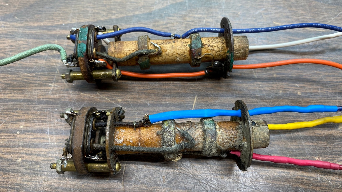
The original 29/45’s 2nd IF transformer (top) and the replacement transformer from a Philco 144 (below).
As you may notice in the photo above, the primary and secondary coils of the 144 IF transformer are closer together than are the original 29 2nd IF transformer’s coils. However, I did not feel this would pose a problem.
I carefully unsoldered the wires of the IF transformer’s coil assembly from the trimmer condenser assembly and separated the two pieces. Then I took the round fiber piece and, with the use of my Ryobi “Dremel” tool, carefully reduced the fiber piece’s diameter so it would easily fit into the 29/44’s 2nd IF shield can.
Once I reassembled the transformer, I rechecked not only the continuity of both coils, but also made sure there were no shorts between windings. All tested fine.
This time, instead of replacing the lead wires, I decided to take the easy way out and simply lengthen the cut leads with new wires and heat shrink tubing.
I installed this IF transformer assembly into the 2nd IF aluminum shield can and wired the leads into their proper places.
I checked for a short at the point where the primaries of IF transformers (18) and (24) connected to capacitor (21), resistor (33), and the resistor I used to replace shadowmeter (27). This time, there was no short to ground. Instead, around 33 to 34,000 ohms was showing between this point and chassis ground. This reflected the resistance of resistor (66), 32,000 ohms, and was expected.
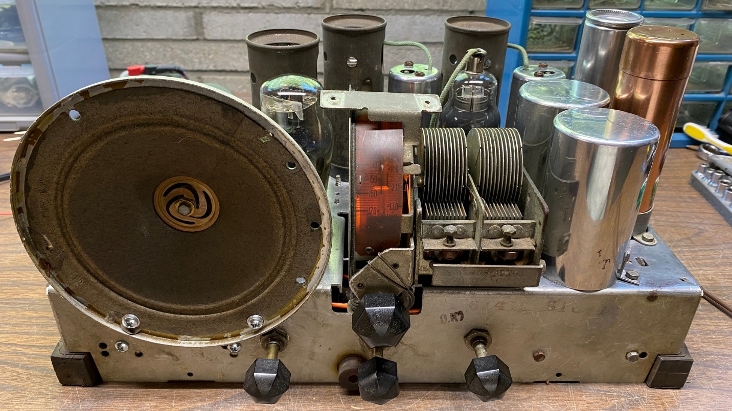
With nothing found amiss, I plugged the radio in and turned it on. There was no smoke. I quickly measured B+ voltage and it was as it should be. Turning the radio off and turning the chassis right side up, I connected my longwire antenna to this 29/45 chassis, and turned it on again.
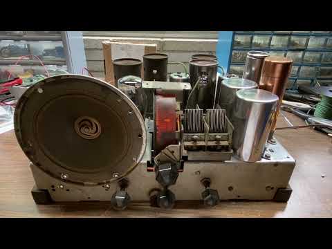
I tuned the radio to my home AM transmitter and as you can tell from the brief video above, was soon hearing the doo wop music which I play on this transmitter.
I tuned across the AM band. The radio obviously needed an alignment, but I could also pick up WITZ in nearby Jasper, Indiana, and WGBF in Evansville, Indiana.
After a break, I went back to my workbench with the intention of giving the radio a complete alignment. Unfortunately, I soon discovered that the holes in the tops of the IF shield cans are not large enough for any of the more recently made nonmetallic ¼” nut drivers to fit through.
Thinking this over, I decided the next morning to try disassembling a ball point pen and using its plastic barrel to make a slimmer tool which would fit through the opening in the IF shield cans. I found a sacrificial pen and pulled it apart, and then pulled out a screwdriver bit with a ¼” hexagonal body, made for use with an electric drill.
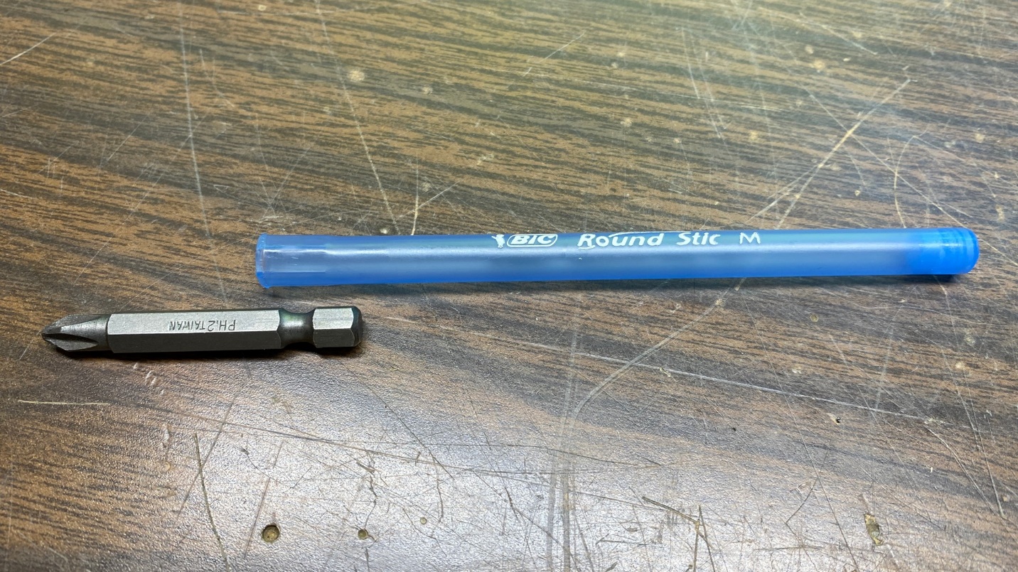
An old pen is about to be turned into a thin-wall ¼” nonmetallic nutdriver.
Using my Harbor Freight heat gun on low setting, I carefully warmed one end of the plastic barrel until it was soft enough to allow me to push the hexagonal end of the screwdriver bit into the end of the barrel. Leaving the screwdriver bit in place inside the end of the barrel, I set both aside until they cooled, at which time I carefully removed the screwdriver bit from the plastic barrel.
I now had a homemade nonmetallic ¼” nutdriver which was slim enough to fit into the openings of the IF shield cans.
Incidentally, it is very important that the tool used for the IF adjustments be nonmetallic. A metallic nutdriver will short the adjustment nut to the aluminum shield, making it impossible to do the necessary adjustments. In addition, even if the tool did not short out the adjustment nut, the steel of the tool would interfere with a proper adjustment of the trimmer.
Now, I proceeded to perform a complete alignment of the radio, starting with the IF adjustments.
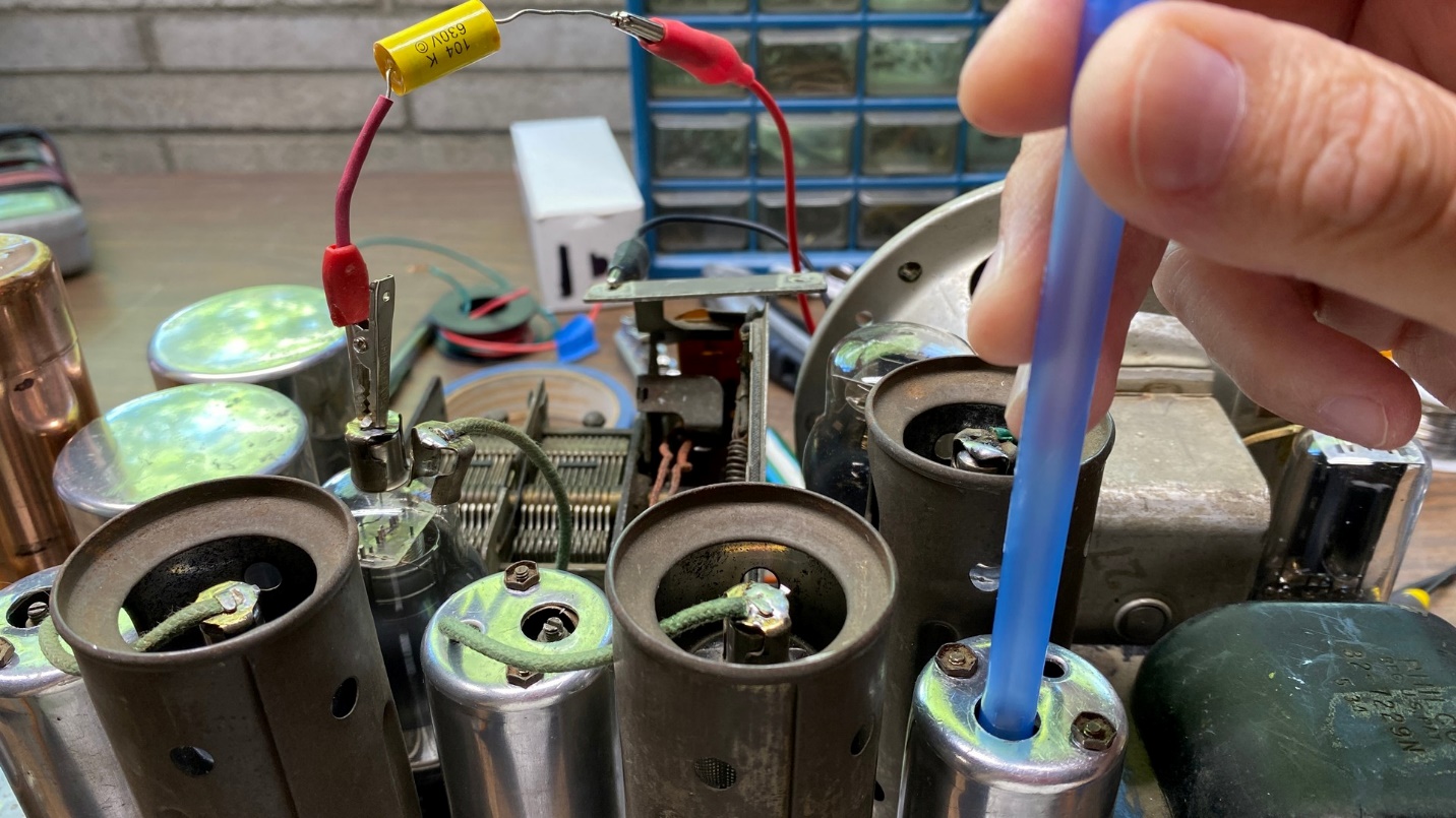
The homemade nutdriver being put to work on the radio’s 3rd IF transformer.
The proper order to adjust the IF trimmers in a Philco model 29 or 45 is as follows: 3rd IF nut, 3rd IF screw (a small screw adjustment in the center of the adjustment nut), 2nd IF nut, 2nd IF screw, 1st IF nut, 1st IF screw. Apply as weak a signal as possible to the radio and use a VTVM connected across the speaker voice coil leads as an output indicator.
This radio does not have any adjustments for its shortwave band; only for the AM band in addition to the IF adjustments. I suggest you find a copy of the John F. Rider book “Aligning Philco Receivers” if you plan to work on multiple Philco radio models. The book was published in two volumes. Volume I covers 1928 through 1937 models; Volume II covers 1938 through 1941 models.
You do not have to look for physical copies of the books, either. Both are available on the wonderful World Radio History website. Here is a link to Volume I; and here is a link to Volume II.
Once I had finished aligning the radio, I replaced the shield over the 6A7 tube (I had to remove it to more easily access its top cap during IF alignment), attached my longwire antenna to the radio, and tuned across both bands. This radio tunes very slowly, making it fairly suitable for tuning shortwave even though its small dial scale is not exactly conducive to shortwave use.
The dim light bothered me. The radio’s original type 46 incandescent lamp was still in place. As I keep a small number of LED replacement lamps in stock, both in bayonet and screw base form, I decided to try one of those. The 46 has a miniature screw base. I pulled out a new LED lamp with a miniature screw base and installed it in place of the 46 lamp. The difference was immediately apparent. Compare the two photos below.
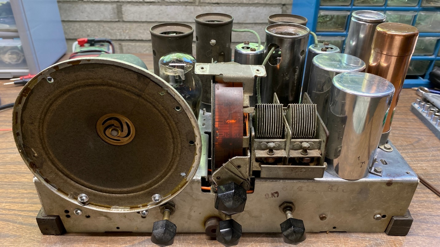
The 29 dial as it looked with the original type 46 incandescent lamp.
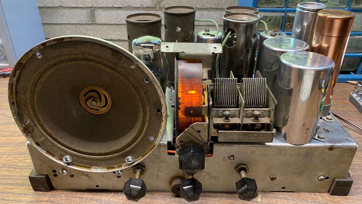
Notice how much brighter the dial is with the LED bulb.
At this point, the radio was basically complete and was working very well. However, I was not totally finished with the chassis. The model 29 power transformer outputs a higher B+ voltage at higher current than does the model 45 power transformer. The P-27 speaker’s field coil is rated for 65 mA, as is the 45C’s original P-19 speaker. The H-16 speaker used with the 29X is rated at 80 mA. So, this project is on hold again until the 45 parts chassis arrives, at which time I will perform a power transformer transplant. This should complete the necessary work on this chassis and will also complete its conversion from a 29 chassis to a 45 chassis. I can then turn my attention to refinishing the “Butterfly” cabinet, since warm weather is now here.