Philco had added refrigerators to their product lineup very late in the year 1938 after purchasing the refrigerator division of Fairbanks-Morse of Indianapolis. The purchase included 35,000 unsold Fairbanks-Morse refrigerators. Philco sold these through the spring of 1939 before bringing out new refrigerators under their own brand just in time for the 1940 selling season which commenced in summer 1939.
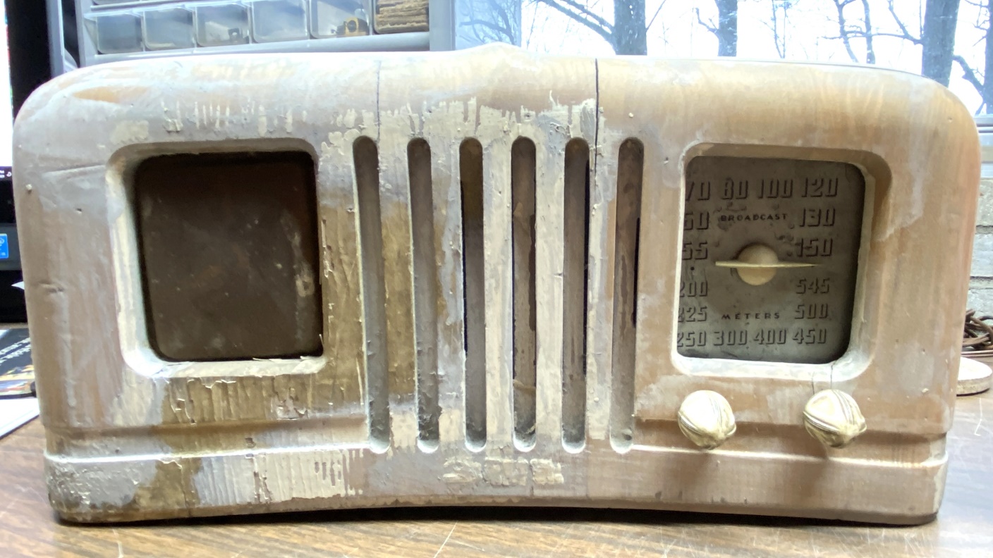
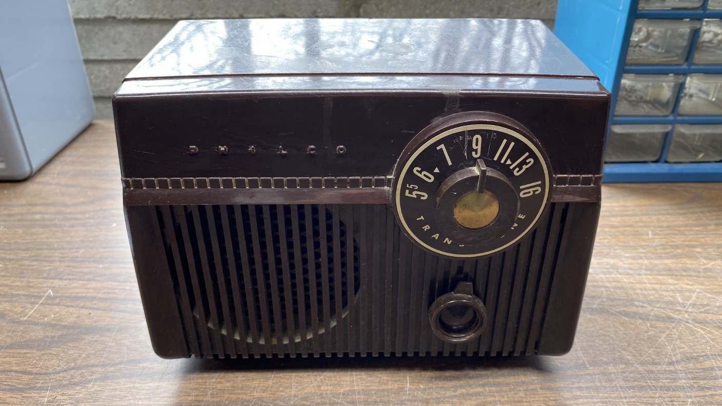
In the summer of 1940, the radio manufacturers began their new 1941 selling season. Now, purchasers of a Philco refrigerator were offered a radio to go along with that new refrigerator. Model 41-KR had a wooden cabinet which was painted white to match the refrigerator and was styled with a curved bottom so the radio could easily fit on top of the curved top of the new Philco refrigerator.
The 41-KR’s radio chassis is essentially the same as the compact, five tube Philco Transitone radios of the period, but added an electric clock.
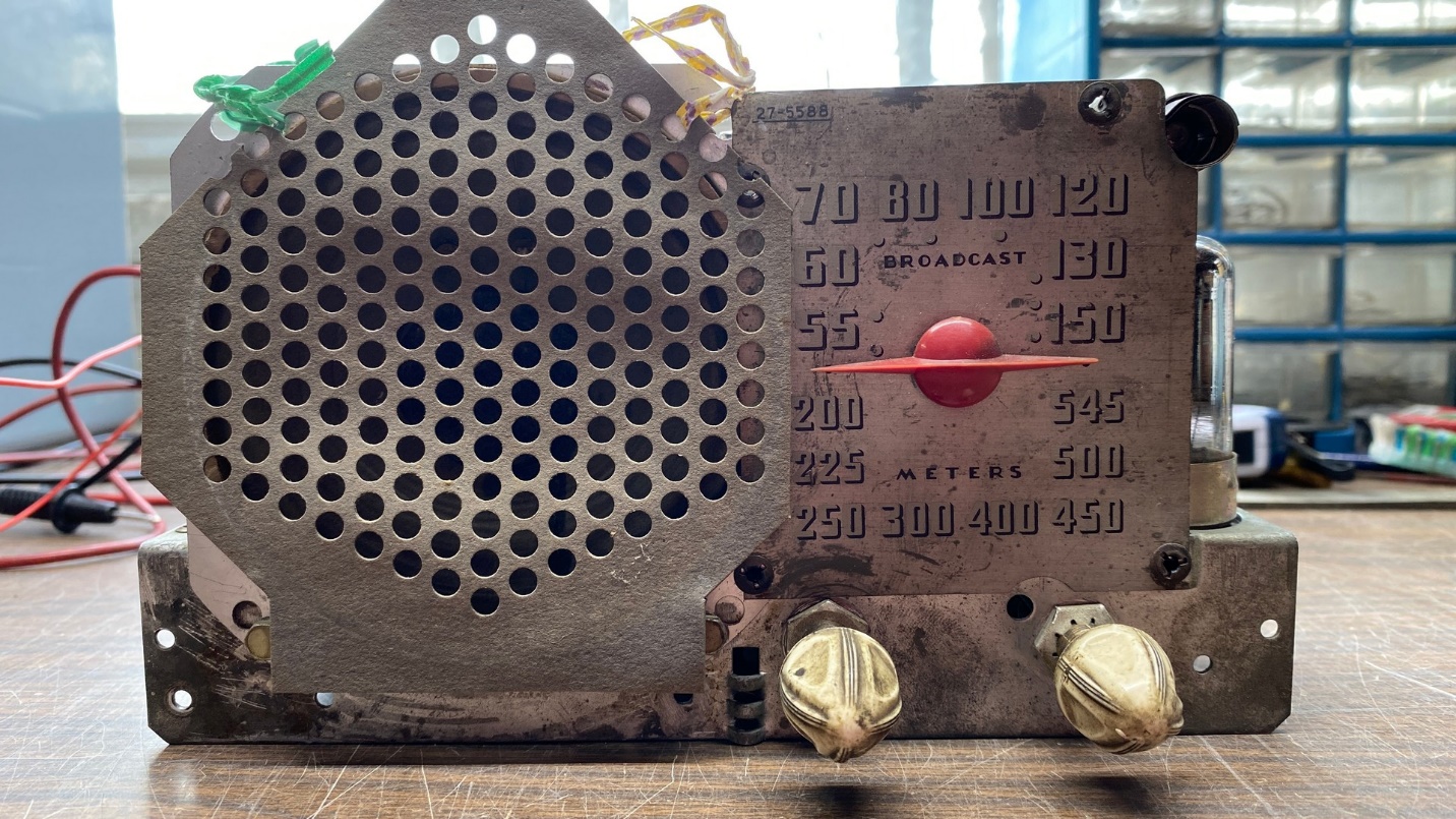
I acquired the 41-KR shown above, in very poor condition, several years ago. I had attempted to strip the cabinet soon after I acquired the radio, but as you can see, my usual recipe of acetone and lacquer thinner only removed part of the finish. I will need heavy duty stripper with methylene chloride, the kind which we can no longer purchase, to finish the job. Fortunately, I still have some methylene chloride stripper.
A word about methylene chloride stripper. Its sale to the public was banned a few years ago after a number of dummies used the stuff indoors, in enclosed areas, then succumbed to the fumes. This stripper is safe to use – provided you use some common sense. Never use it indoors. Always use it outside where you can get plenty of fresh air. Use heavy rubber gloves.
In any event, any further cabinet work will have to wait until spring of this year, once temperatures get warm again.
It has been my Christmastime tradition for several years now to pick a radio and try to get it going in time for Christmas. For Christmas 2021, I chose the chassis of this 41-KR.
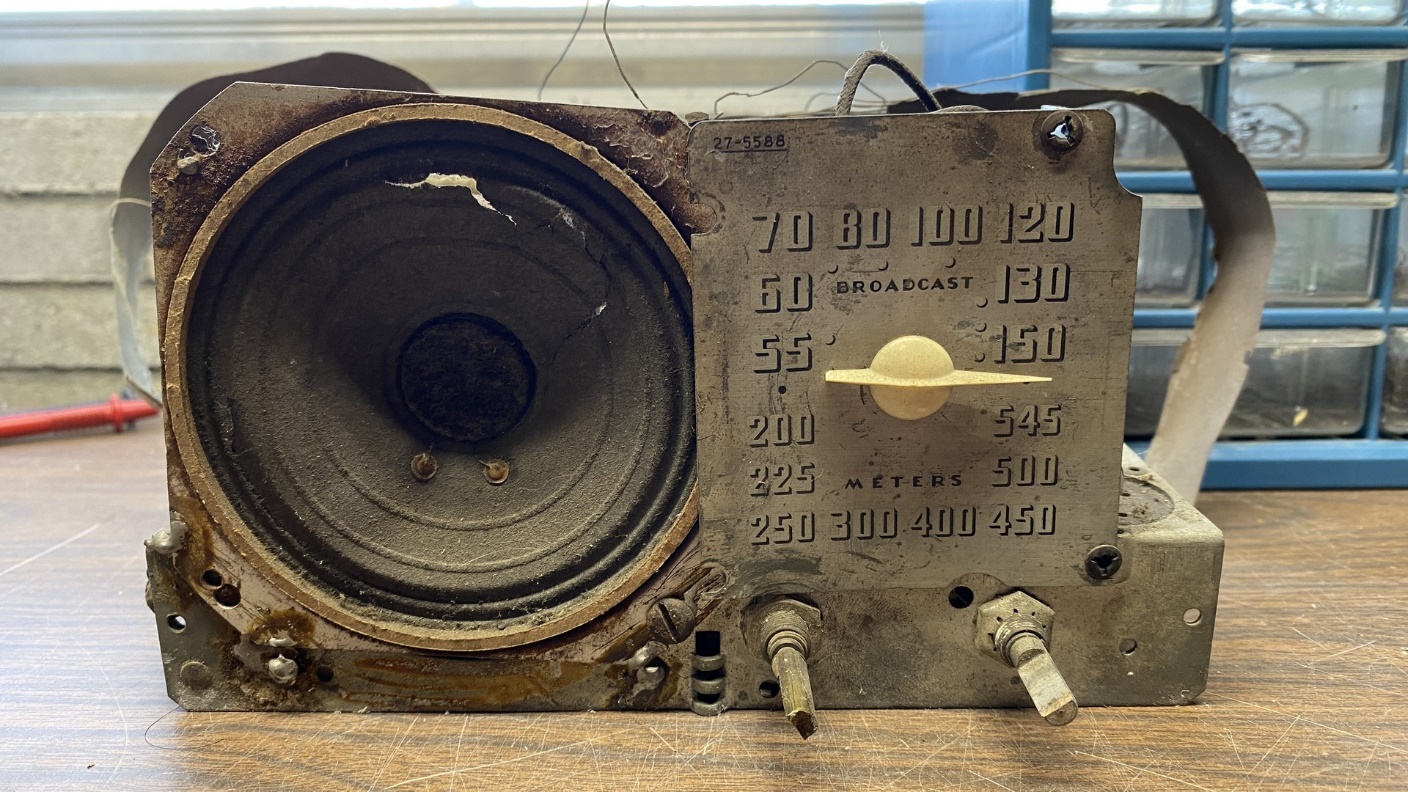
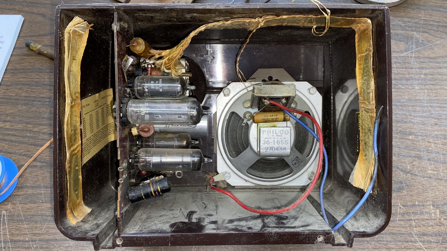
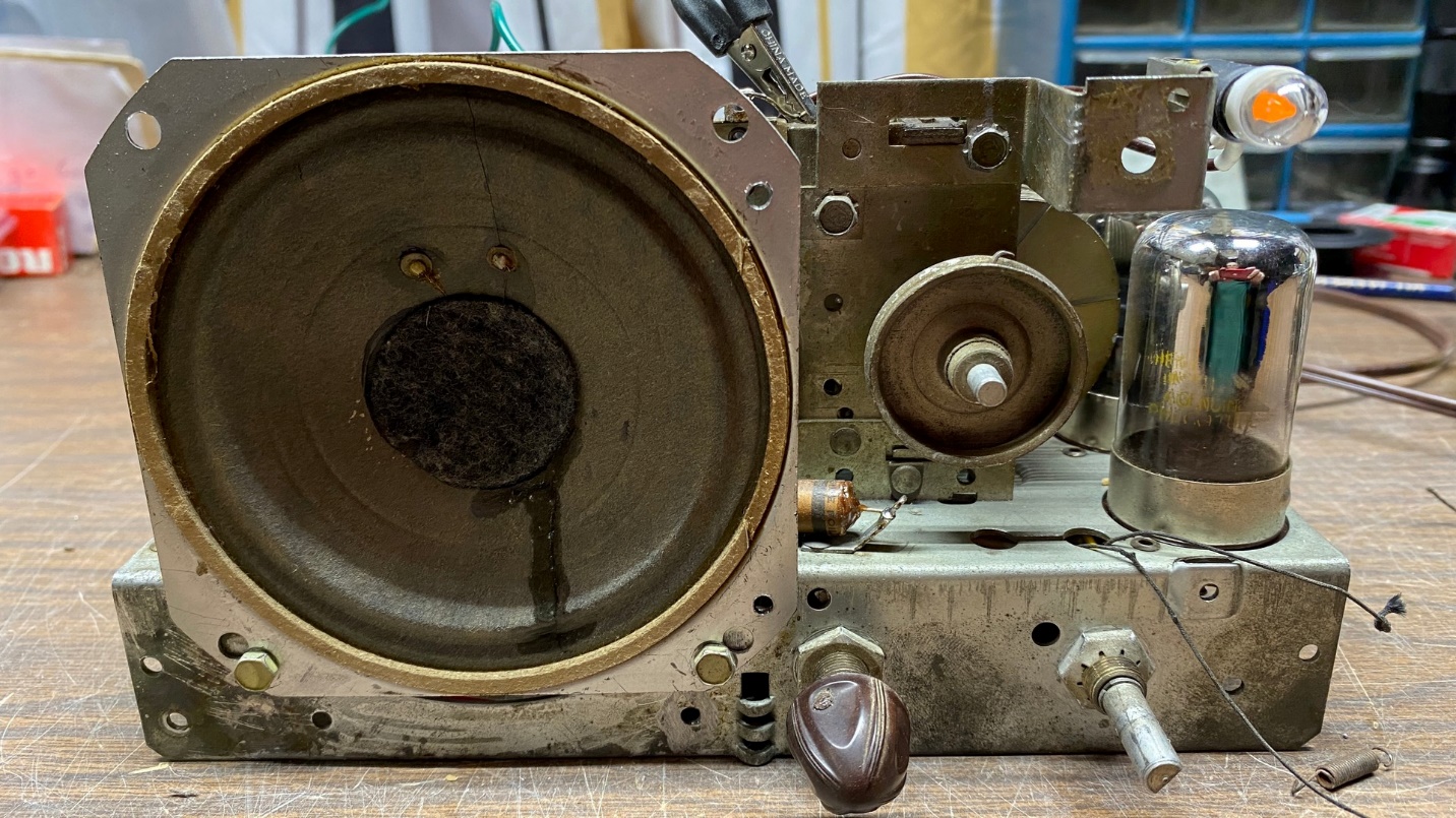
The chassis of the subject Philco 41-KR.
As you can see, the chassis is almost as rough as the cabinet. The speaker, a Quam replacement, was sloppily installed and the cone is torn. The dial scale is dull, faded and generally poor.
The set’s loop antenna is in very poor condition and will have to be replaced.
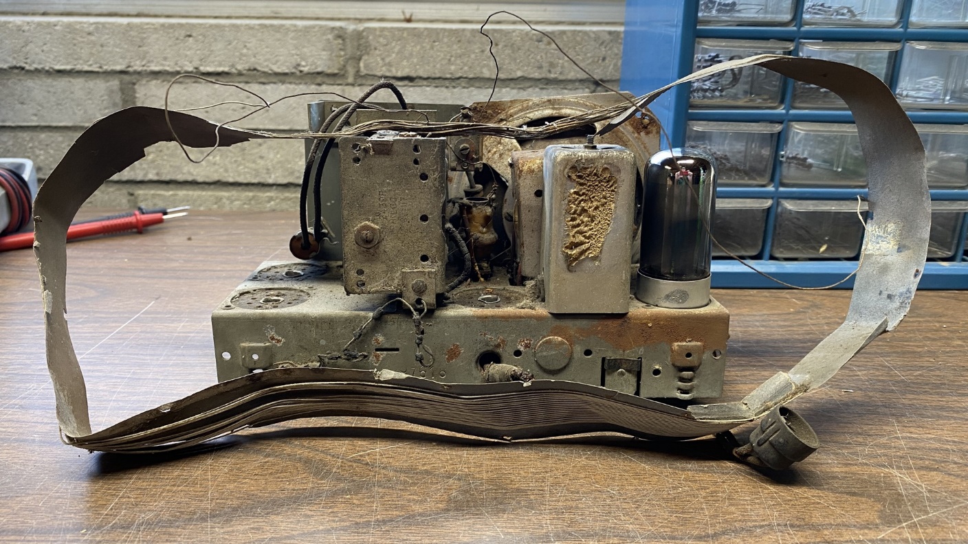
This radio uses a loop antenna, which mounts inside the cabinet. It is designed for the chassis to sit on top of the loop.
This loop antenna is in very rough condition, and it is going to have to be replicated somehow.
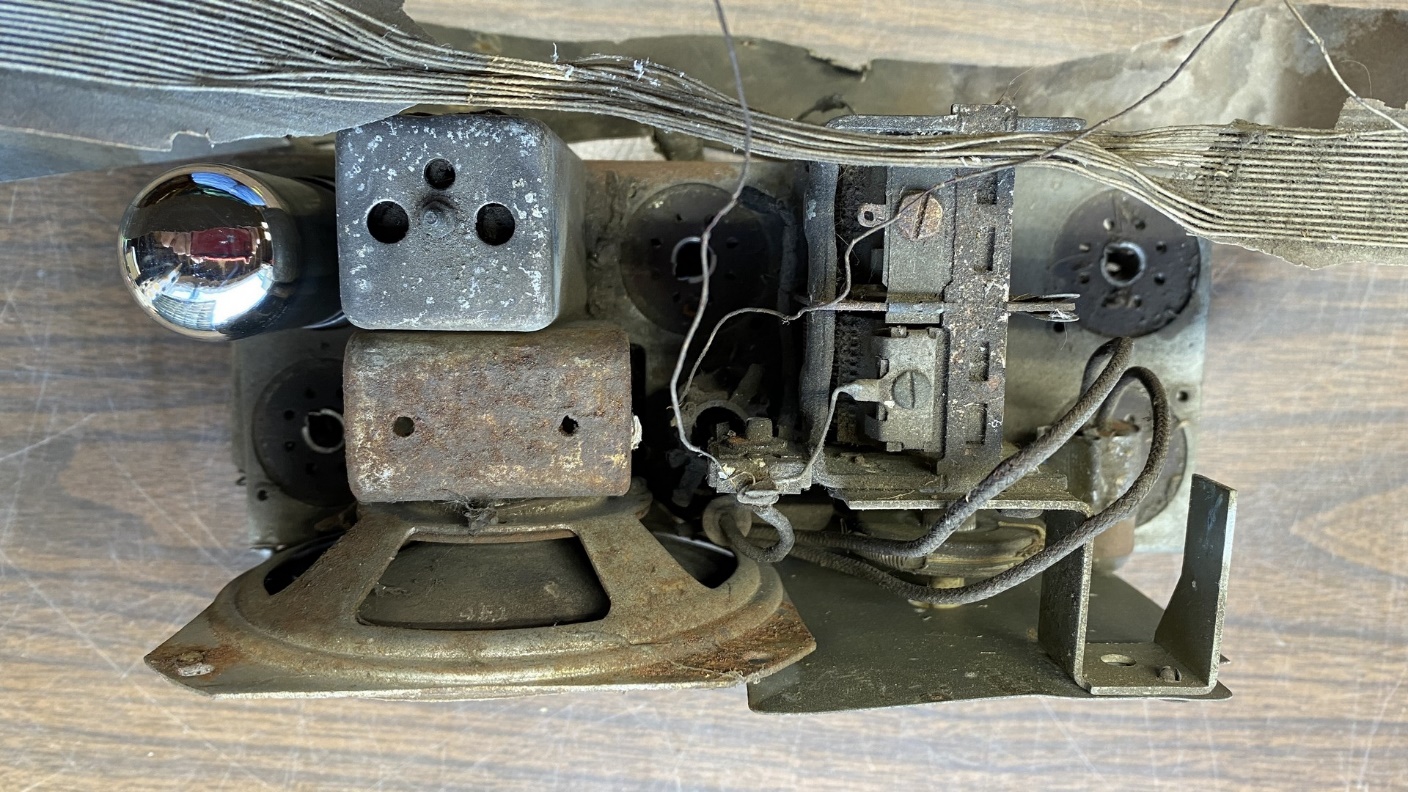
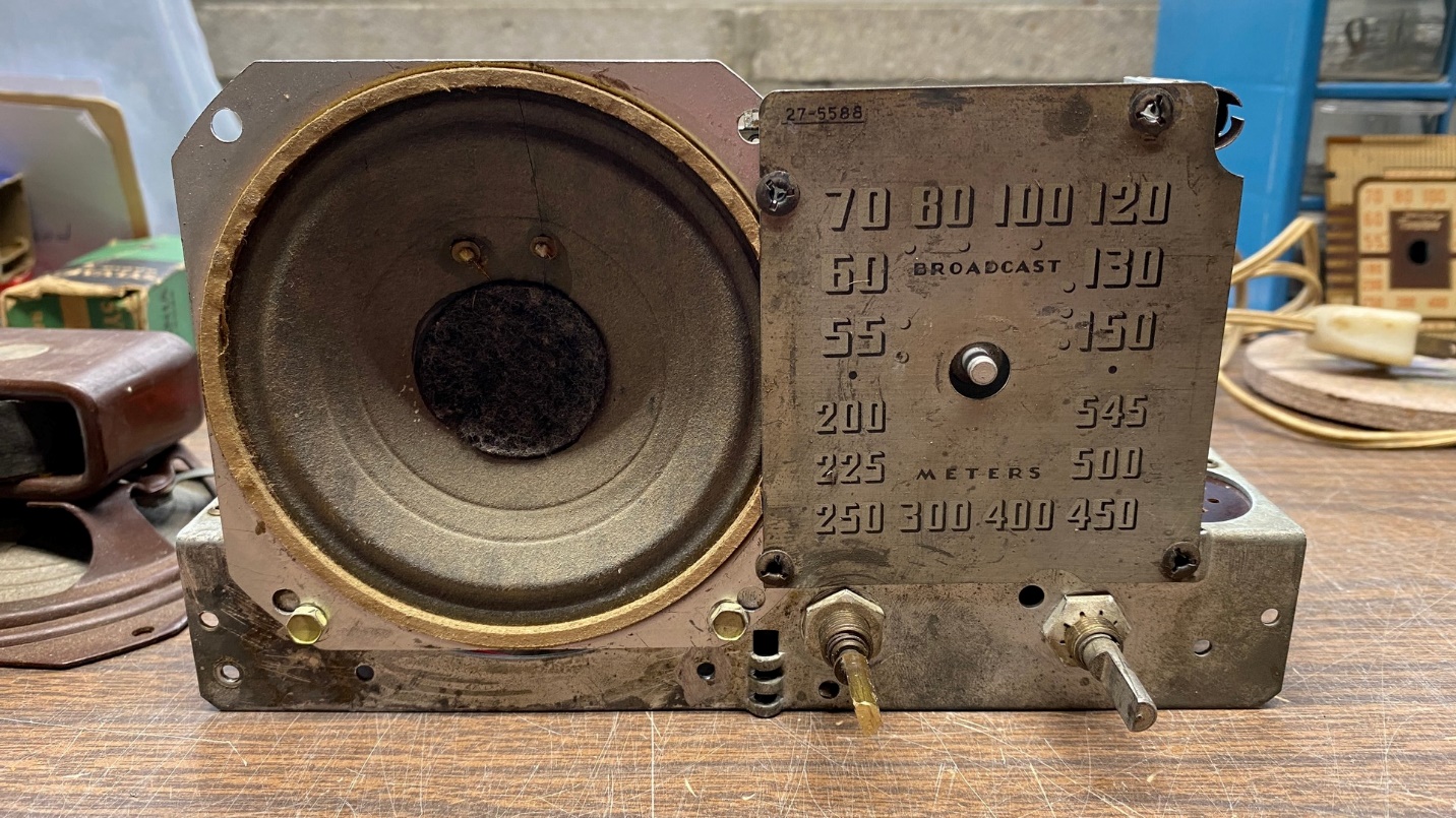
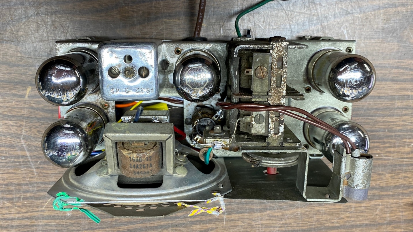
Top view of the Philco 41-KR chassis.
You can see the top of the chassis above. Again, it is in pretty rough shape.
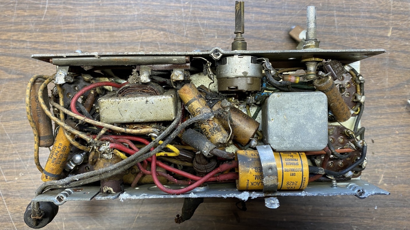
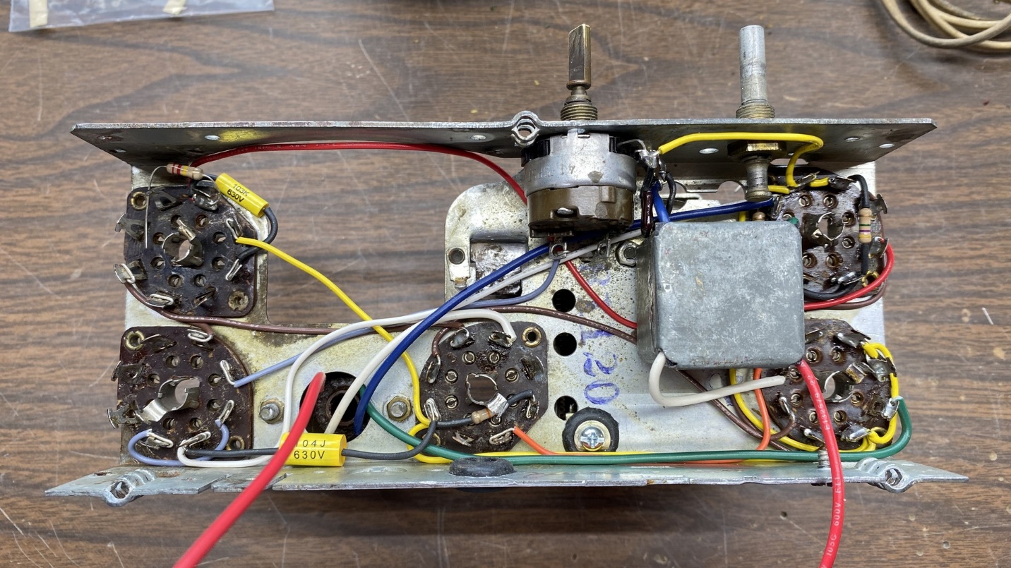
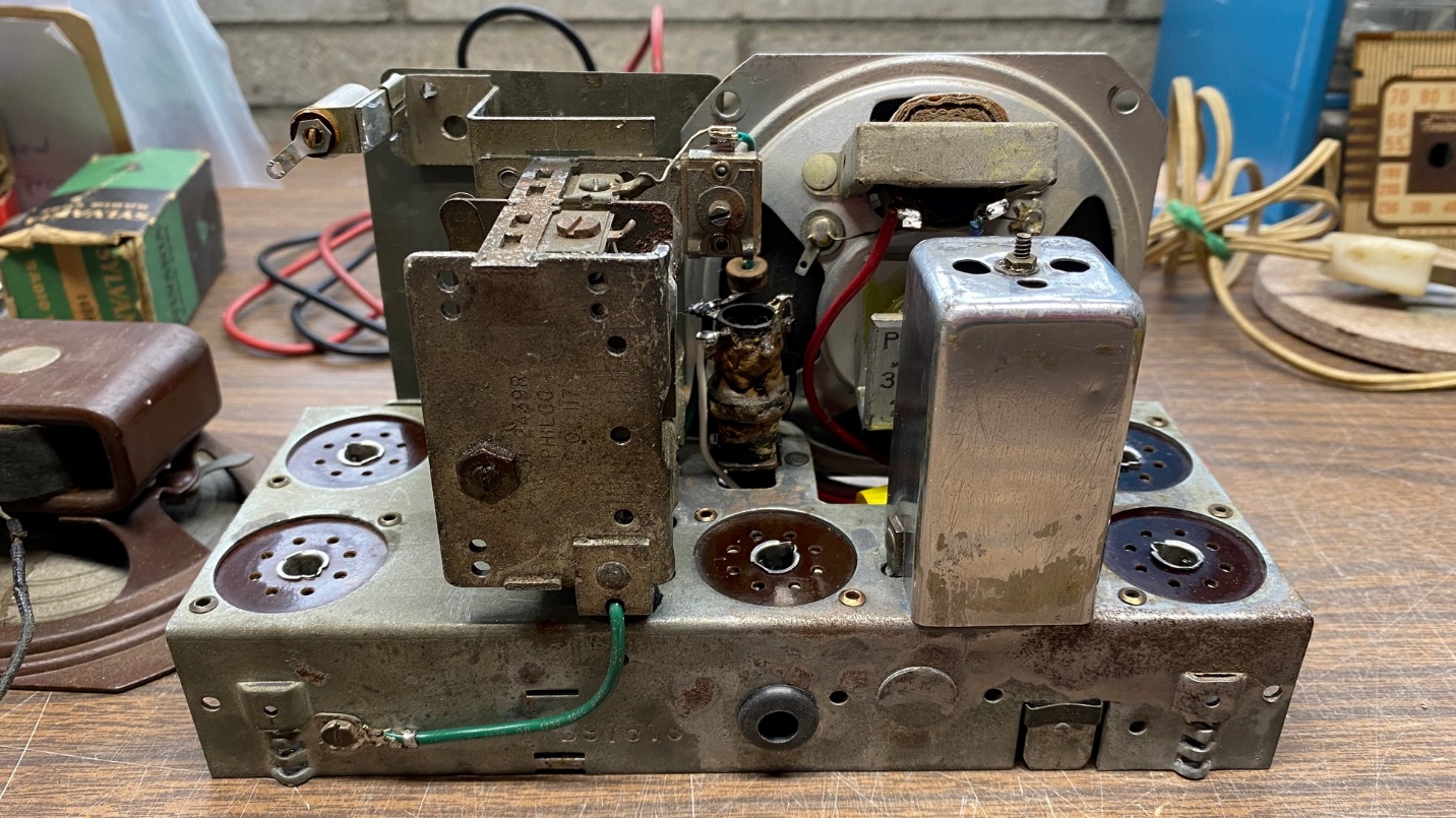
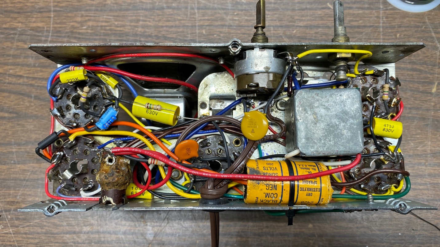
Bottom view of the Philco 41-KR chassis before rebuilding began.
Taking a look under the chassis, you can see how tightly packed the wiring and components are – typical for these very small five tube Transitone chassis.
Philco used wiring with rubber insulation when they built all of their radios made between 1939 and 1942. This was fine when the sets were new. But 80 years on, time has not been kind to the rubber insulation on that wiring. Most of it has now dried out and is flaking off the wires. If a rubber-covered wire is now disturbed, the insulation will usually fall off.
I have found there is only one way I can deal with these little Transitone radio chassis.
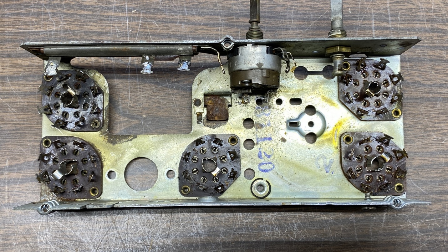
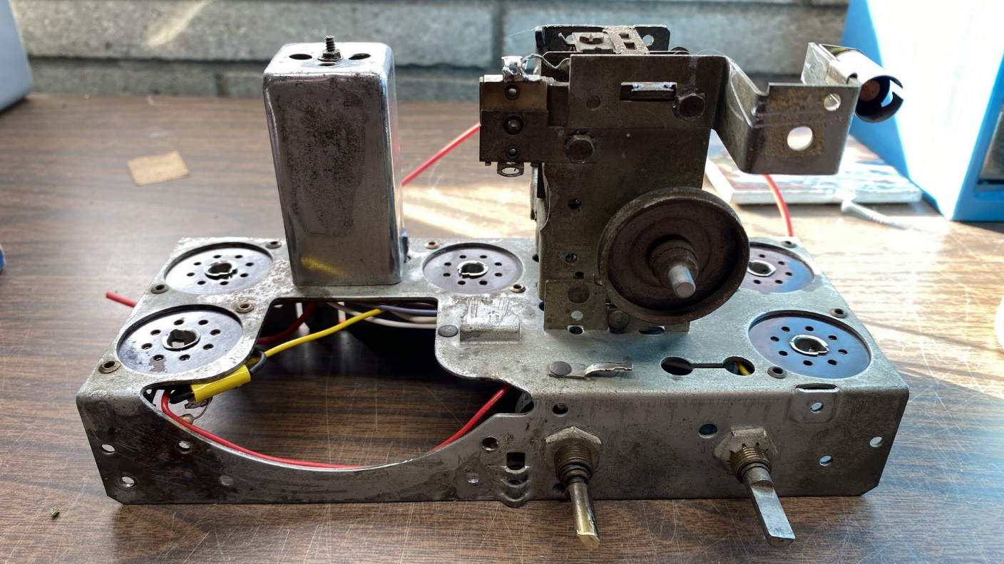
A bare Philco 41-KR chassis.
That’s right – as the photo above suggests, I simply strip everything from the chassis, all the way down to the bare chassis and tube sockets.
I have found it is easier to first strip, and then rewire the set using new wiring. By doing so, I know the set will be safe, with no insulation issues, for many more years.
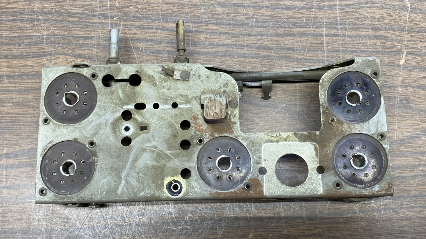
Top view of the bare 41-KR radio chassis.
The chassis had some rust spots. I did not trust soaking the entire chassis in Evapo-Rust, my rust cleaner of choice for rusty metal, as I did not know what effect the Evapo-Rust might have on the tube sockets; chiefly, the space between the phenolic wafers which make up each tube socket.
So, I used Evapo-Rust Gel instead. The gel does not compare to the regular Evapo-Rust product, unfortunately, and provided poor results.
I ended up scraping as much rust as I could off the worst spot on the chassis, the bracket which holds the antenna coil in place.
Since I was completely rebuilding the radio, I decided to take advantage of this by incorporating some improvements.
This radio, as with all the compact five tube Transitone chassis, incorporates a voltage dropping resistor in the filament string. I decided to change the tube lineup so no dropping resistor would be required.
Fortunately, there are loctal tubes which have higher filament voltages but are otherwise equivalent to the tubes I wanted to replace.
After consulting with my favorite online tube database – that maintained by Bill’s Ham Radio Web Server at nj7p.org – I soon learned that yes, I could easily do this, and without changing tube sockets.
The 14B8 is electrically equivalent to the 7A8. In like manner, I found that I could use a 14A7 for a 7B7; a 14B6 for a 7C6; and a 50A5 for a 35A5. Finally, using a 35Y4 for a 35Z3 would give me a tapped heater, allowing use of a dial lamp without the need of a resistor.
I made a few modifications to the 41-KR schematic. The image below shows that modified schematic.
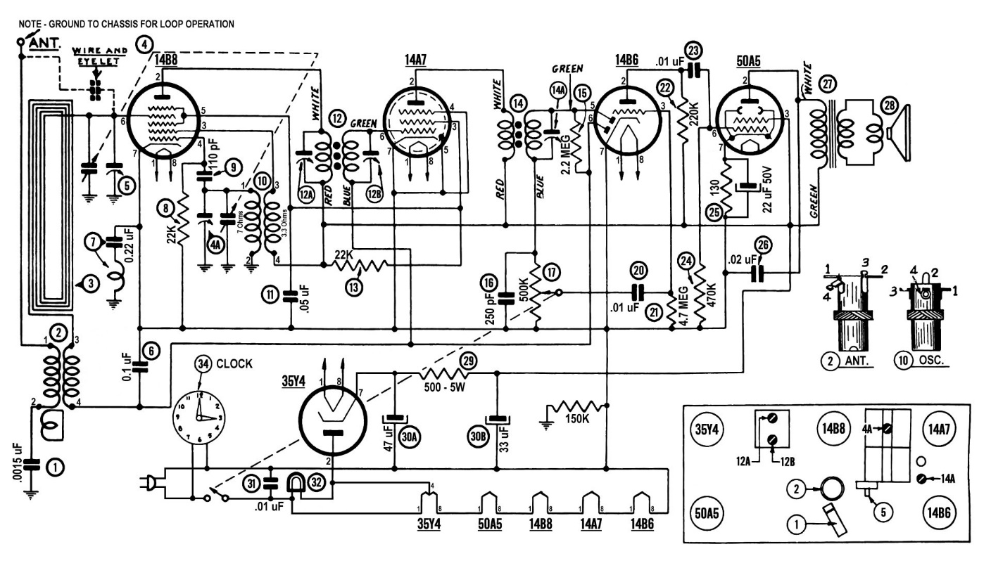
Philco 41-KR schematic, modified by the author to eliminate the need for a filament dropping resistor.
In the schematic above, I also plan to move the power switch to the hot side of the AC line and use a new line cord with a polarized plug to ensure the switch will always be on the hot side of the line. I am also going to remove a resistor and capacitor connected between the wiper arm of the volume control and part (20) above. I will also add a 22 uF, 50 volt electrolytic between the 50A5 cathode and B-, to give this tube a bit more amplification.
I will change the original .03 uF capacitor, part (31) above, to a .01 uF X1-Y2 safety capacitor which is designed to fail open.
You will notice that the radio’s original field coil, part (29), will be replaced with a resistor. I planned to use a 500 ohm, 5 watt resistor. Unfortunately, I found that I did not have any such resistors in stock. Therefore, I will use a 250 ohm, 2 watt resistor instead, the same as I used in my recent modified Philco 54C project. This resistor’s value is not very critical.
Of course, I will also have to rebuild the loop antenna. I do not plan to do this until after the cabinet has been stripped, repaired, and repainted.
I began to rewire the chassis, first by connecting the filament wiring, and then some of the B- wires.
Soon, it was time to deal with the two IF transformers.
Rebuilt 1st IF transformer (left) and unrestored 2nd IF transformer (right).
Other than having to replace the can shield, the 1st IF transformer was easy – disassemble, replace wires, polish the replacement can, reassemble.
The 2nd IF transformer was a different story. Encased within a shielded can which had been soldered shot on all four sides, it was a real pain to get three of the sides unsoldered so I could open the can. But I eventually prevailed, and you can see the open can above.
The disassembled 2nd IF transformer.
Now, with the transformer itself removed from the can, I proceeded to replace all four of its lead wires as you may see below.
New wires have been attached to the 2nd IF transformer.
Afterward, I reinstalled the transformer into the can. This time, I only soldered the can in one spot, just enough to hold the can shut.
1939 and some 1940 Transitone models used a 2nd IF transformer with no shield can. Sometime during the 1940 season, Philco switched to using an IF transformer with a can. Of course, a shielded transformer is better overall, but Philco obviously never intended for these cans to be opened and repaired.
The rebuilt 2nd IF transformer.
The rebuilt 2nd IF transformer was eventually ready to be reinstalled in the radio chassis.
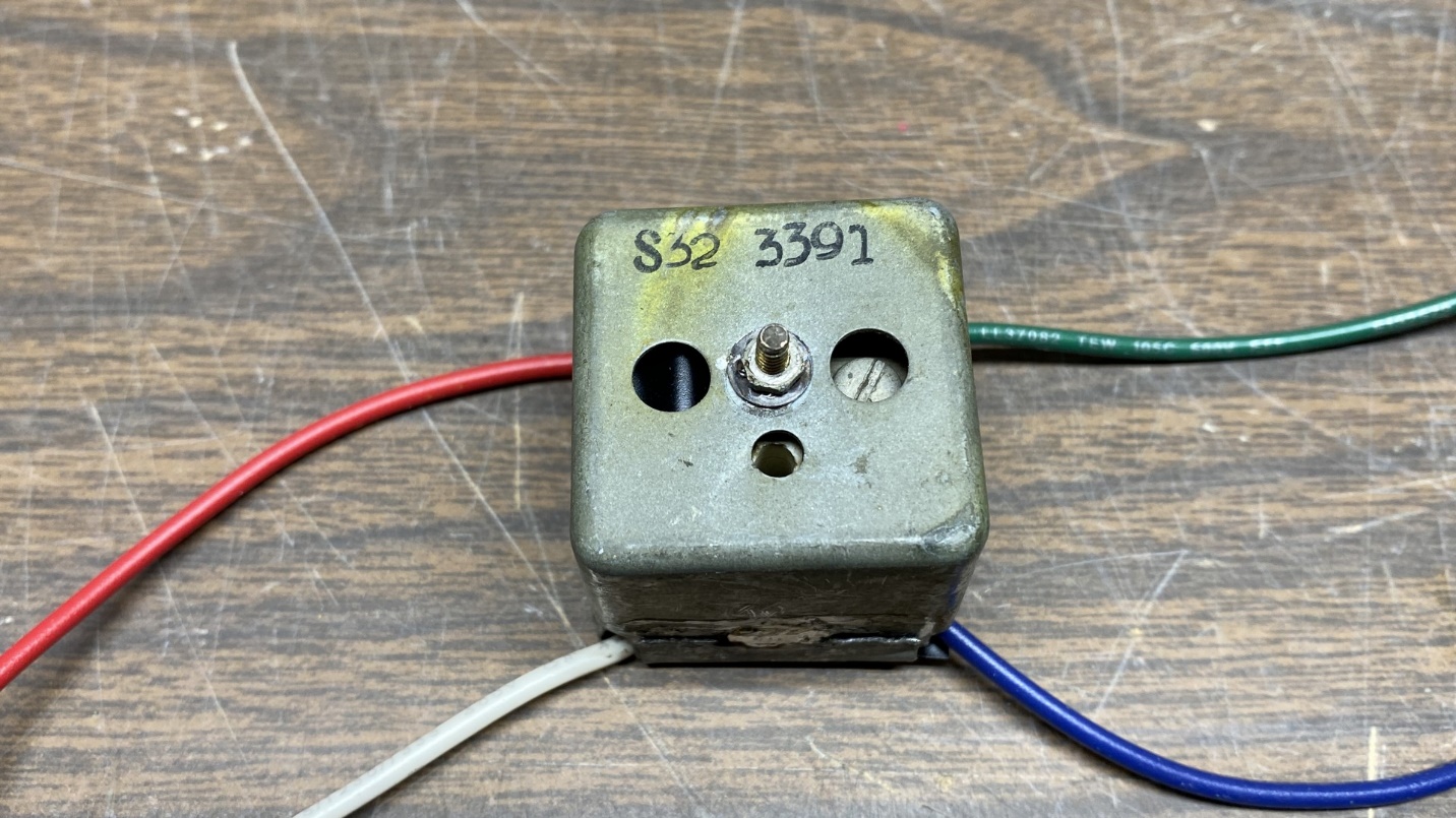
This unit is ready to be reinstalled in the 41-KR radio chassis.
Once it was back in place, I continued to install wires and various components.
And at this point, I can see that this is turning into a very long post. Therefore, I will pause for now and resume next time with the remainder of the 41-KR chassis rebuild. Please make it a point to join me here then.
My 2021 Christmas Radio – Philco 41-KR Chassis Rebuild – Conclusion
Progress on replacing wires and components.
When we left off last time, I had just finished rebuilding the two IF transformers of this little Philco 41-KR radio and had installed the 2nd IF transformer in the chassis. Now, it is time to continue the work on this set.
The 1st IF transformer and the tuning condenser were eventually put back on top of the chassis.
The chassis is slowly beginning to look like a radio once again.
Before long, I reached a point where I needed to install a speaker.
I had purchased a rough plastic radio just to get a 4 inch square speaker with an audio output transformer meant to match a 50C5 output tube attached to the speaker.
A 1955 Philco C579, purchased with the express purpose of using its speaker and output transformer in the Philco 41-KR chassis.
The radio, a 1955 Philco C579, was a four tube “gutless wonder” with a simple pentode autodyne mixer and no IF amplification.
As the 50A5 and 50C5 both have a 2500 ohm output impedance, this combination of output transformer and speaker were perfect for the 41-KR.
Back view of the C579 with the back cover removed.
I removed that paper capacitor you see in back of the speaker above, and then installed the speaker on the 41-KR chassis.
The C579 speaker is now installed on the 41-KR chassis. A test fit of the metal dial has also been made.
Before installing it, however, I had to drill some holes in the frame – two new mounting holes as the mounting holes of the original speaker were drilled off center, and two smaller holes to help hold the metal dial scale in place.
Fortunately, I was able to drill these holes without damaging the speaker cone.
The chassis is almost finished at this point.
The output transformer was small enough that the speaker could be installed as shown above, and it will not rub against the top of the radio’s cabinet. This allows a bit more real estate below the chassis for wiring and components, in the space where the radio’s original audio output transformer was once placed.
A restuffed electrolytic condenser, ready to install into the 41-KR chassis.
Using a new 47 uF, 200 volt electrolytic and a new 33 uF, 200 volt electrolytic, I stuffed this old cardboard tube and it became the new main filter condenser for the radio.
The underside of the 41-KR chassis after rebuilding was complete.
Here is how the underside of the chassis looked after everything had been installed. As you can see, it is just as tightly packed as it was originally, even though I used new yellow film capacitors and did not bother to restuff old paper capacitors here. These little Transitone chassis need all the space they can get.
The 41-KR chassis is ready for its first test run.
You can see a line in the speaker cone where there is fabric glue. Yes, I clumsily poked a finger through the cone while finishing up under the chassis.
Fortunately, fabric glue does a great job of repairing torn cones.
A protective cover is placed over the 41-KR’s speaker.
After tearing the cone once, I wasn’t going to take any more chances, and temporarily covered the front of the speaker with the same fiber shield which was used when the speaker was mounted inside the C579 radio.
I used twist ties meant to hold bread wrappers closed to hold the shield in place. I will leave this over the speaker until the cabinet is redone and ready to receive its rebuilt chassis.
Oh, and you have probably noticed the radio now has a red dial pointer. The original pointer was broken. I will paint this replacement pointer white to match the original when spring returns.
Top view of the completed 41-KR chassis.
On Christmas Eve, after putting everything together, I temporarily connected a ferrite rod antenna from the C579 to the 41-KR in place of its loop antenna, and tried the radio out.
It made a strange low-pitched squeal and motorboated a bit on the low end of the AM band. On the upper end, AM sounded fine.
I had accomplished my goal – I heard the radio play just in time for Christmas.
A few days later, I decided to try a test by bypassing the loop with a piece of wire, and using the antenna lead connected to my longwire antenna. This time, AM worked across the entire band. This was a relief, as I now knew that the squealing and motorboating I heard on Christmas Eve was caused by the ferrite rod and not by any wiring inside the chassis.
I aligned the IF transformers and found that only one of the adjustment screws was off. I will perform the RF alignment later, after I have fabricated a new loop antenna for the radio.
And that concludes the electronic restoration of this Philco 41-KR. When warmer weather returns in spring, I will tackle the cabinet, revisit the dial cord on this chassis (it is currently slipping badly), and decide what to do about a clock. The cabinet will also need new clear plastic dial covers for both the radio dial and the clock. I will deal with those issues at that time. Thank you for reading.