As you recall from Part 7 of this series, I had performed an alignment of the RCA T9-10 chassis. I was now using two 20 dB attenuators in series with my function generator’s output cable, and the extra attenuator seemed to help reduce the output signal to a more usable (i.e. lower) level for vintage radios. It would probably benefit from a bit more attenuation, however. But I digress.
Band B of the radio was basically not working, and I had decided to remove the band B antenna coil from my T8-14 parts chassis and substitute it for the coil in the T9-10. Therefore, I moved the T9-10 chassis aside, and placed the T8-14 parts chassis back on the bench.
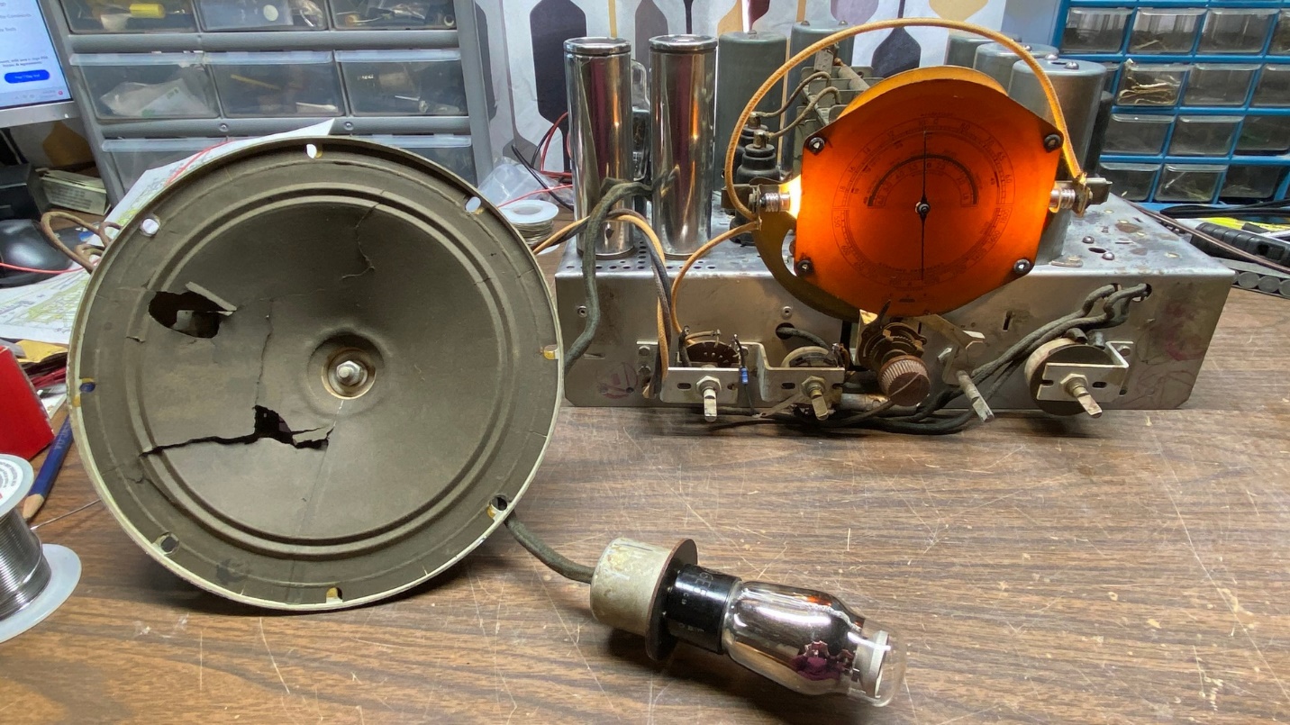
The RCA T8-14 parts chassis was now back on my workbench.
Turning the chassis upside down, I unsoldered the leads from the band B antenna coil (L-e, L-4, C-2 on the schematic). I then turned the chassis right side up and removed the two mounting screws. The coil then fell out and onto the bench.
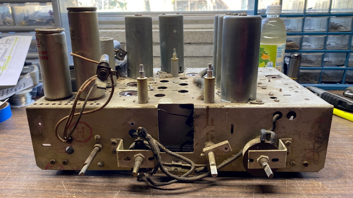
The band B antenna coil may be seen just to the right of the antenna coil for bands A and C.
Once the coil was out of the parts chassis, I repeated the procedure on the T9-10 chassis to remove its band B antenna coil.
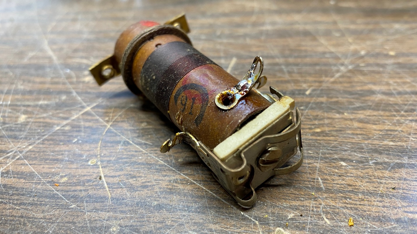
The coil from the parts chassis has its terminals desoldered and is now ready for installation into the T9-10 chassis.
It was then a simple matter of installing the coil into the T9-10 chassis and soldering the leads to the appropriate terminals on the coil.
I then hooked up the function generator and tried the radio out on band B again. However, I discovered that band B still did not work!
I then did some careful circuit tracing, and soon discovered a mistake I had made.
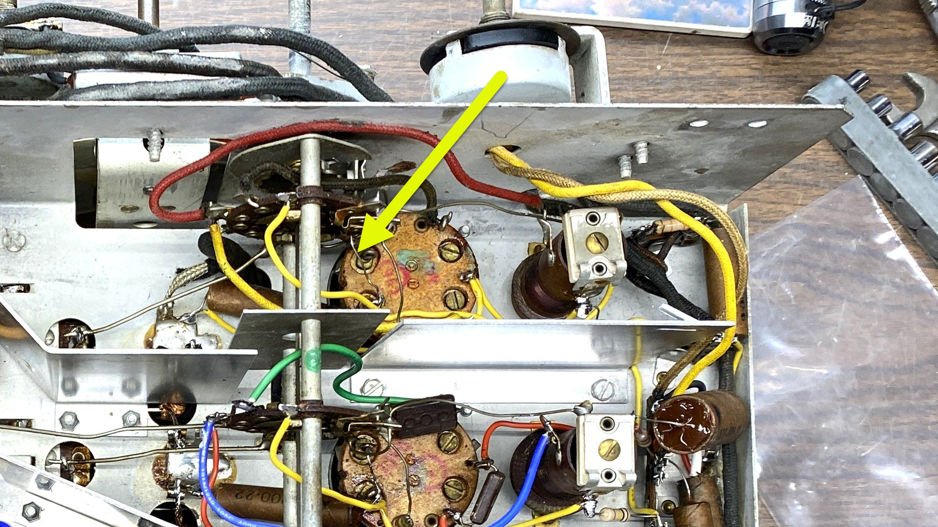
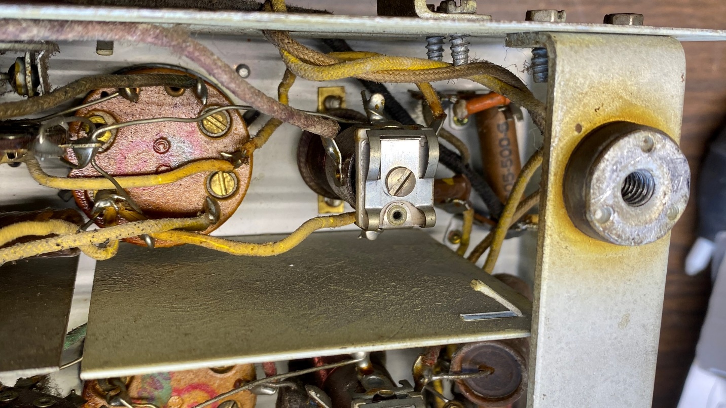
The yellow arrow points to a long bare lead which should not be there.
In installing the restuffed C-4, .047 uF, I had forgotten to snip the excess lead length where it was soldered to a terminal of the bands A and C antenna coil. This excess lead had come into contact with a terminal of the band switch which affected band B, effectively disabling band B in the process.
With the chassis off and unplugged, and the function generator disconnected, I cut the excess lead length and removed the excess lead wire.
Then, I reconnected the function generator, turned both radio and generator back on, and was then able to properly align band B.
So, band B was now working as it should. Upon examining and testing the original band B antenna coil, it seemed to be ok after all. However, I had already gone to the trouble of making the replacement and so I left the T8-14 coil in place inside the T9-10 chassis.
Final Notes
The “repairman” who had added the phonograph input and switch in back of the chassis had cut the shielded cable which originally ran from the volume control to the grid cap of the 6F5 audio amplifier tube, and routed it to the added radio-phono switch instead. I could have used new shielded cable, but I opted to use the original cable from the T8-14 parts set for the sake of original appearance. This worked out well and did not create any problems.
The radio seemed to perform very well on all bands now. I was very pleased at how things had turned out, considering how rough the chassis seemed to be in the beginning.
I noticed that I had not replaced the mica capacitor and the small resistor (C-21 and R-4, respectively) which are mounted on the back of the tuning condenser and are part of the radio’s oscillator circuit. However, since the radio was working so well with the original parts in place, I decided to leave them as is – again, for the sake of giving an appearance of originality.
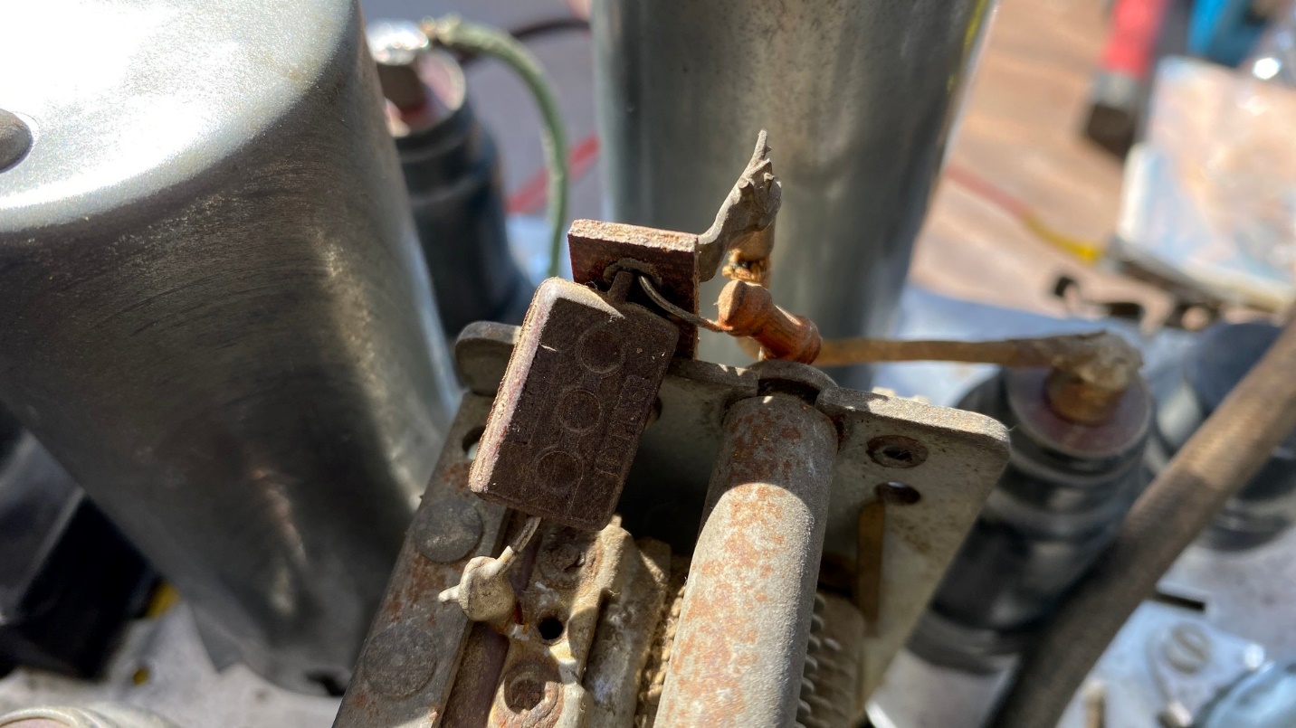
Original C-21 and R-4 remain mounted to the back of the radio’s tuning condenser.
And I just realized that I never told you what I did about the open Candohm resistor (R-18 & R-19). Well, once again, the T8-14 parts chassis came to the rescue as its R-18/R-19 Candohm was good! I removed both Candohms by grinding off the heads of the rivets, and then attached the good Candohm to the T9-10 chassis with pop rivets. This allowed me to preserve the mostly original appearance of the chassis.
Now, I had tried to fill in the holes in the back of the chassis, which were left by the removal of the radio-phono switch and the phonograph pin jacks. with solder. But this did not work out very well. I then decided to simply cover the holes with a reproduction label.
RCA placed a label near the antenna and ground Fahnestock clips of their 1936 radios. I had previously removed the fragments of the old label as I was cleaning the chassis. However, the T8-14 parts chassis had a (mostly) intact label. I carefully took a photograph of that label, trying to get the camera angle as correct as I could so the resulting label would be as “square” as possible.
No one makes this label, so using the photograph I had taken of the old one, I made a new label of my own. See photos below.
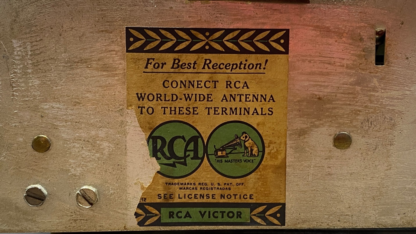
Label affixed to the back of the RCA T8-14 parts chassis.
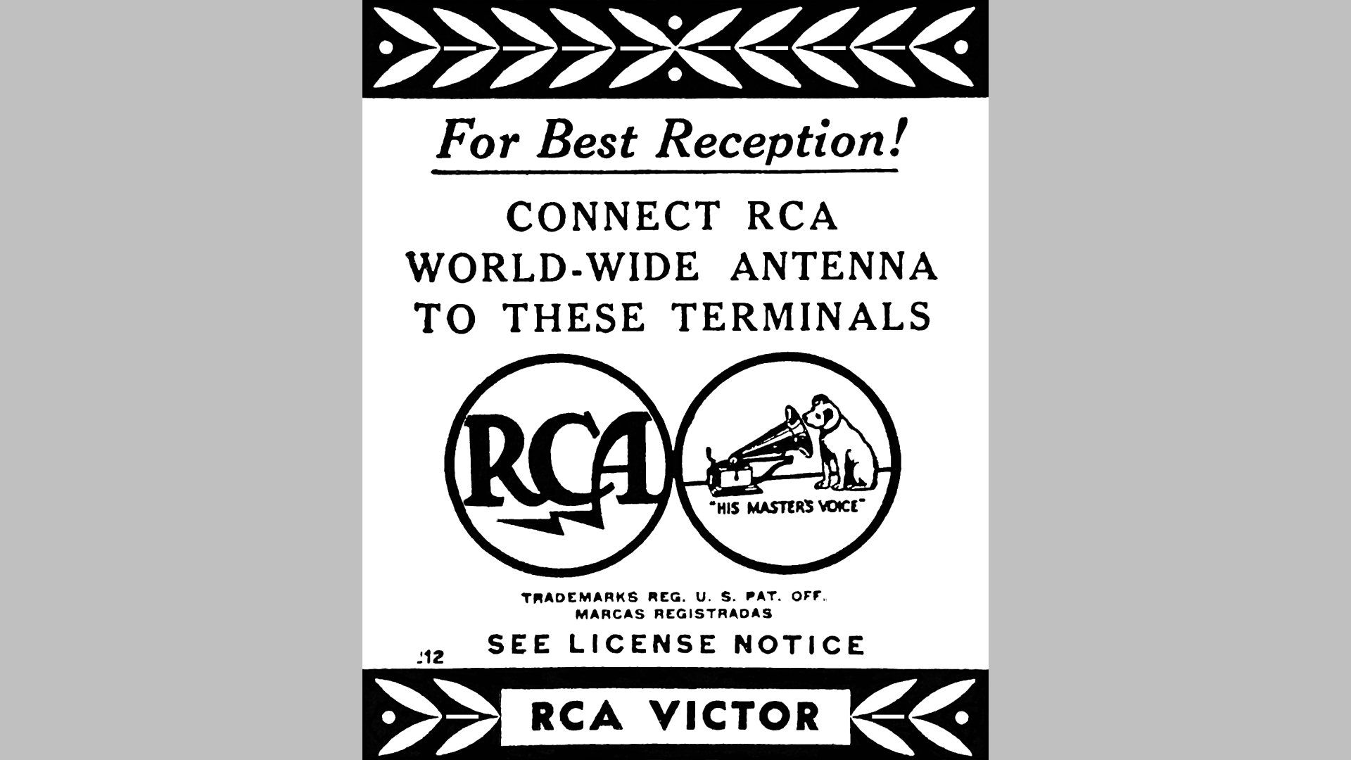
The re-created label.
Adding the missing section of the RCA “meatball” logo was not easy but, as it turned out, not too difficult either. However, the missing bottom decorative edge was easy to replicate – I merely copied a section of the right side of this bottom edge, made a mirror image of it, and pasted it into place. You can see the results above after the image had been converted to gray scale, color corrected, and touched up.
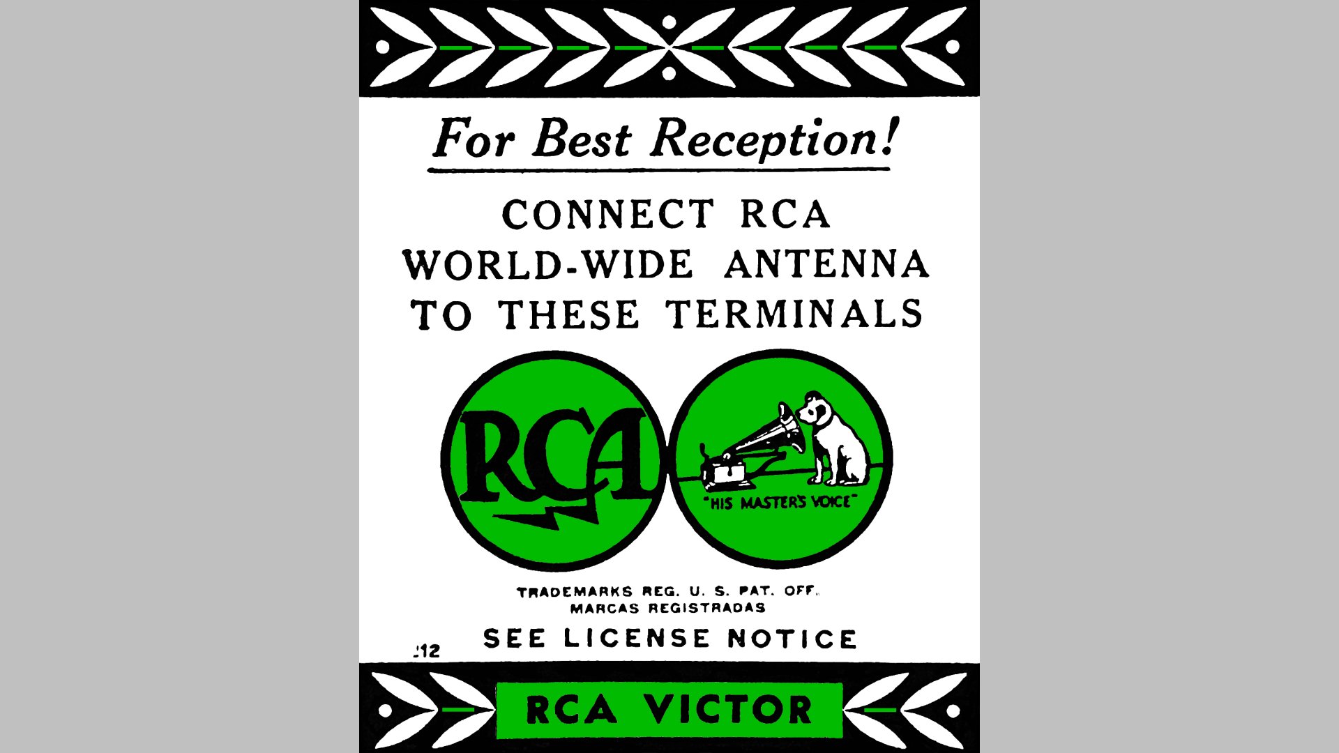
The reproduction label with the green color added where needed.
Once I had a good black and white image of the label, I added the green color to the areas where the original label had green in it.
Finally, I printed a new label. Since I did not have any “aged” or light tan paper, I added my own light sepia tone to the image and printed it on plain white paper. The new label was then cut out and glued over the holes in the chassis using super glue.
I have made a full size image of this label available at the Philco Phorum so you may download and print your own.
Here is the finished product.
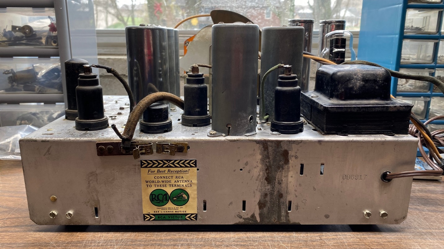
Back of the RCA T9-10 chassis with reproduction label attached.
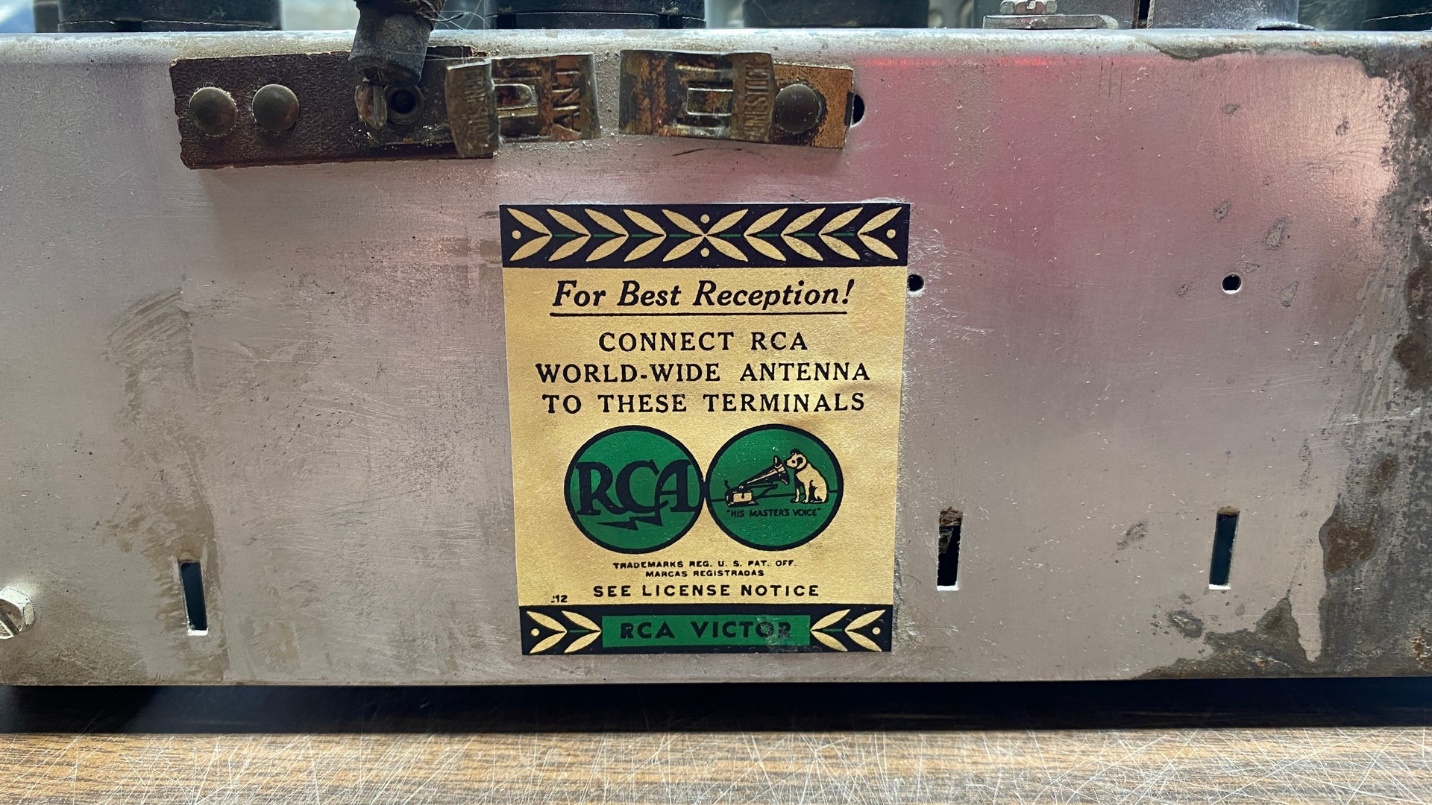
Close-up of the reproduction label.
You will note a couple “lumps” in the label; those are caused by the label resting against two rivet heads. The label therefore could not lay completely flat against the metal. (This is why the original label had been placed just to the left of the new label, where it could lay flat against the metal.) But at least those ugly holes are now covered up.
And that is it for this complete restoration of an RCA model T9-10. The work began in late January and was not finished until mid-March. Yes, I still need to order and install two tubes and have the speaker reconed, but once that is done, the electronic restoration will be complete. It looks good once again and plays very well.
Lord willing, this summer I hope to be able to refinish its cabinet.