The 1936 RCA Victor model C15-3 console radio is an excellent receiver, as it should be with 15 tubes on its large, heavy chassis. With an RF amplifier stage and two stages of IF amplification, you would expect it to be very sensitive – and it delivers once properly restored. Unfortunately, it does not have the high fidelity capabilities of its 1937 sibling, model 15T, but still delivers great sound with its big (and heavy) 12 inch speaker.
I am sure that one of these radios could easily pull in all the shortwave one could want back in the bygone days of international shortwave broadcasting.
I bought this radio in May 2018, at the last Kutztown swap meet I attended before the cancer diagnosis. I restored its chassis in the summer of 2019; you may read about that here. The cabinet is in very good shape save for the top, which is warped and delaminated. I solved that problem by placing a doily across the top of the set, and my more recently acquired Atwater Kent 10-A breadboard now resides on top of the RCA. This hides the flaws of the C15-3’s top.
I have one of the SStran AMT3000 AM radio home transmitters, which was a gift from Debbie several years ago. (These are no longer being produced.) I had not used it for at least two years as I had lost interest in listening to AM radio after the cancer diagnosis. There is little to hear on AM where I live. There is only one local station, which went to an all-Spanish format a few years ago. There are a few stations in Evansville, Indiana and Owensboro, Kentucky, but they usually come in weakly. It does not help that our home is located in a geographically low area.
Recently, I learned about software to turn one’s computer into an automated radio station. It is called RadioDJ, and you can learn more about it here. I decided to download it, install it on an old laptop, and program it to play popular music of the early to mid-1970s which I loved listening to as a youngster.
My RCA C15-3 is located in my home office, and I wanted to be able to hear my new 1970s era Top 40 radio station when in my home office as well as in my basement while working on another project. Long story short – RadioDJ was set up on the old laptop. The SStran was retuned to 890 kc from its initial setup frequency of 660 kc, following the tuneup procedure in the SStran manual. The laptop was then attached to my SStran and put on the air.
I was disappointed to find that the reception on my C15-3 was spotty at best, with the signal coming and going.
So, I felt it was time to give that RCA a tuneup.
I pulled the big, heavy chassis out of the large cabinet and managed to get it downstairs to the workbench. I then began to go over the chassis with the proverbial fine-toothed comb.
I checked the continuity of the AM band antenna and RF coils. These were fine. I then checked the IF transformers. These likewise all had good continuity. I did notice, however, that two of the IF transformers – specifically, the 2nd and 3rd IF transformers – had some components hidden inside which I had missed in my initial restoration of the radio in 2018.
I proceeded to remove the 3rd IF transformer from the chassis. This is what I found inside:
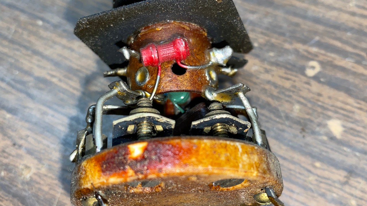
A look inside the C15-3’s 3rd IF transformer.
The transformer had an old 175 pF mica capacitor and two carbon resistors (56K and 220K) inside. I decided that the best course of action would be to replace these with new components.
Mica capacitor inside the 3rd IF transformer.
This was accomplished easily enough, and the 3rd IF soon had two new resistors. I replaced the 175 pF mica capacitor with a 180 pF C0G/NP0 ceramic capacitor since this is what I had on hand. I felt the slight discrepancy in its value would not cause a problem.
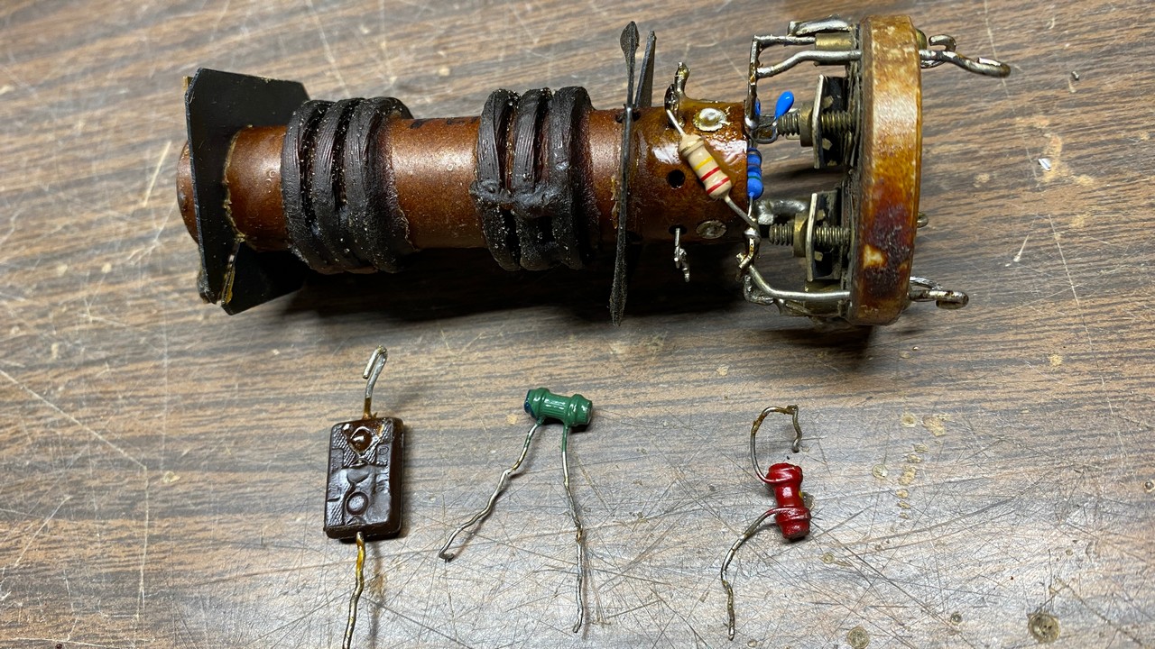
The 3rd IF transformer with new components. The old parts may be seen next to the transformer.
Having replaced the components, I reinstalled the 3rd IF transformer in the radio chassis and then removed the 2nd IF transformer.
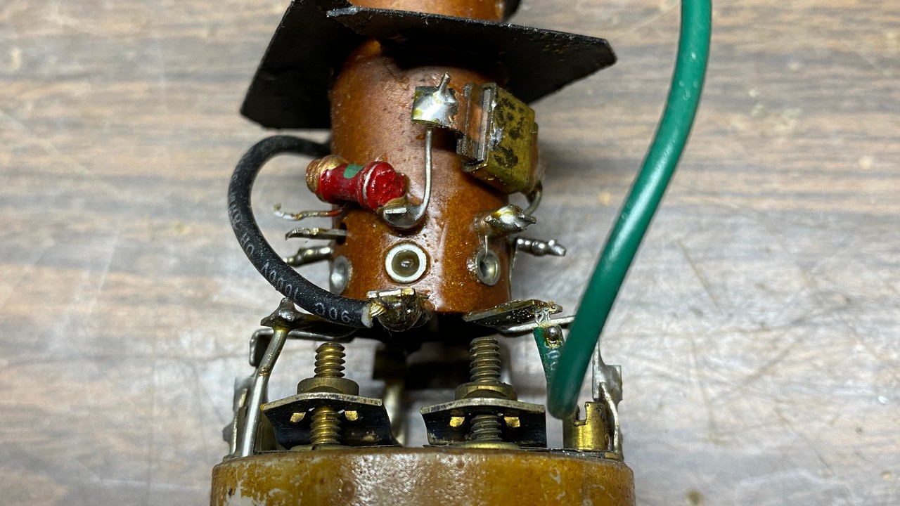
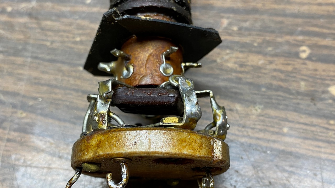
The RCA’s 2nd IF transformer, showing a resistor and capacitor.
This unit contained a 265 pF mica capacitor and a 2.2 megohm resistor. Notice in the photo above that the mica capacitor is not the sealed type, but an “open air” type which RCA sometimes used in radios they manufactured in the mid-1930s.
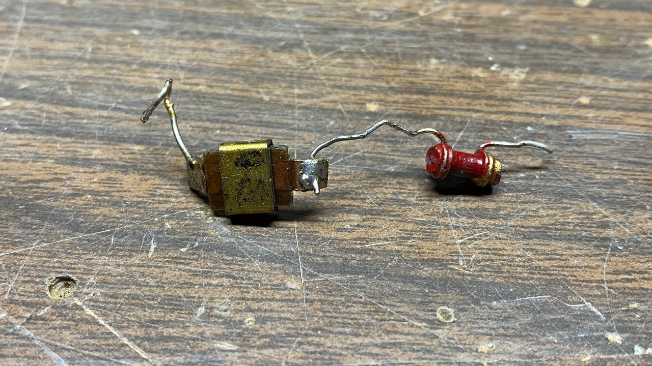
The old parts removed from the 2nd IF transformer.
I replaced the resistor with a new 2.2 megohm, ½ watt resistor. The capacitor was replaced with a 270 pF C0G/NP0 ceramic capacitor. Again, I felt the slight discrepancy in value would not cause an issue with the radio’s performance.
Once the two components were replaced, the 2nd IF transformer was reinstalled in the radio chassis.
Now that that was done, I began to look for any other problem areas. I noticed the speaker wires were frayed where they exited the chassis. See photo below.
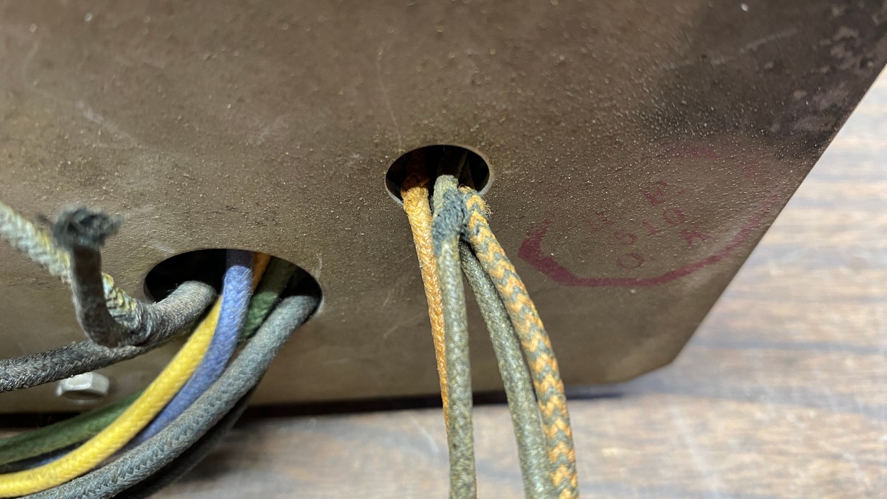
Fraying of speaker wires caused by their rubbing against the hole in the chassis over the decades.
I wonder how I missed that issue five years ago?
Anyway, I knew I needed to address that problem. I constructed a new speaker wiring harness using new cloth-covered wire from Antique Electronic Supply. This particulalr wire is rated for use up to 600V, and as such, it is thicker than the “unrated” cloth-covered wire which was formerly sold by Radio Daze. (While Radio Daze still lists this wire, they only have stocks of white and blue wires remaining.) However, the thicker 600V rated wire should easily last another 90 years or so.
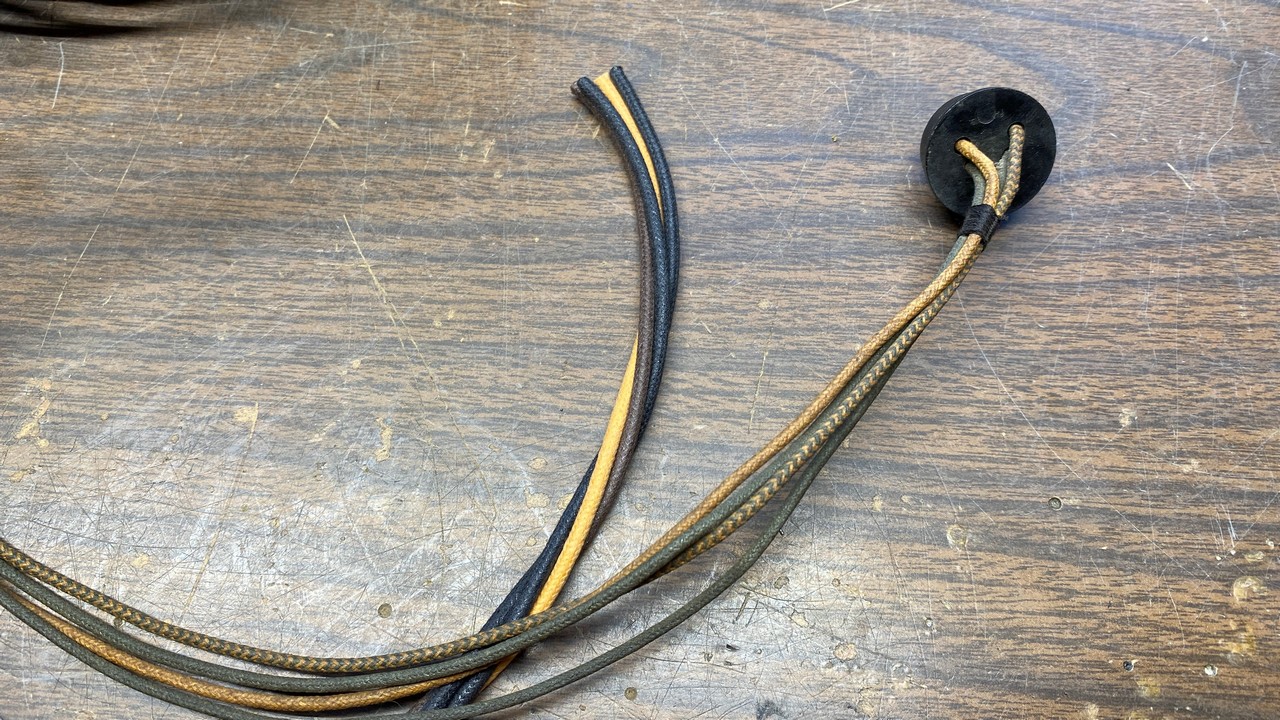
New speaker wiring harness next to the old harness.
With all the chemotherapy I have been through, it is much harder now for me to twist the wires together to make a harness. However, I persevered, and succeeded in doing so.
I would need to connect a four-pin jack to the end of the harness to connect to the matching plug on the radio’s speaker. I found that I was not able to remove the rivet holding the insulator over the top of the original speaker jack. Therefore, I decided to use a speaker jack from a 1946-48 Philco radio.
A Philco part in an RCA radio? Horrors! But seriously, the Philco jack had the same pinout as the RCA jack and would mate nicely with the RCA’s speaker plug. The pins of the parts are the same size, also, so this replacement would pose no problems.
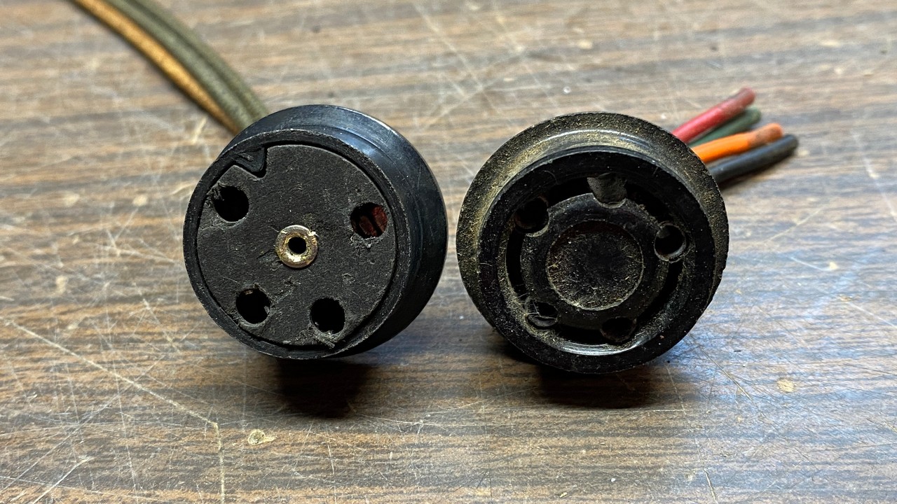
The original RCA speaker jack (left) and the replacement (right), taken from a 1946-48 Philco radio.
There are two ways to use the Philco jack. You could splice each of the wires from your speaker wiring harness to the existing wires protruding from the Philco jack. But a neater (although harder) way is to remove each of the four pin connectors from the jack, remove the old wires, solder the new wires to the connectors, and push them back into the jack.
Each connector must be carefully pushed out the back of the jack. This can be done with a small screwdriver.
Once I unsoldered each of the old wires, I soldered the new wires to the connectors. Then, using a wiring diagram which is included as part of the RCA factory service data for the C15-3, I carefully pushed each of the connectors back into the jack, being sure to put each wire/connector combination in the proper hole so the speaker would work properly.
Did I mention the word carefully?
Well, I slipped on one of the connectors while pushing it back into the jack – and broke off a piece of the jack!
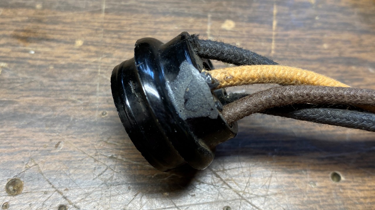
The repaired speaker jack.
Without the broken piece of plastic, the connector would not lock into place in the jack. I therefore got out my tubes of J-B Weld, mixed a little, and glued the broken piece back onto the jack, using masking tape to hold it in place while the glue dried.
The next day, the jack looked as shown above.
I then soldered each of the four wires inside the radio where each needed to go. I added a knot just inside the chassis at the point where the wires exit the chassis through the hole in front of the chassis.
I also added a rubber grommet to protect the new wires from rubbing against the metal.
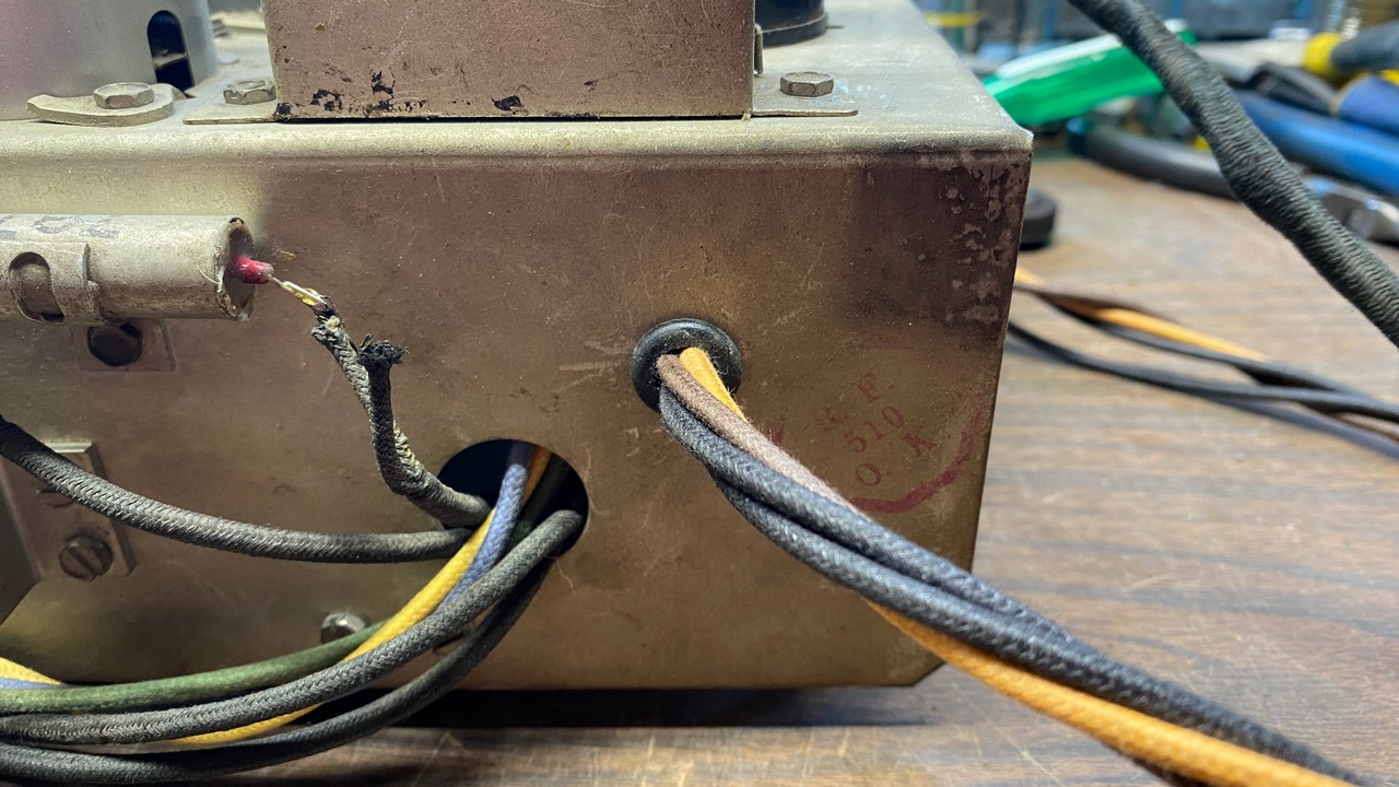
A rubber grommet now protects the new speaker wiring harness.
I decided I should test the RCA’s tubes, but only those from the front end through the second detector as the audio section of the radio seemed to be fine. I therefore tested the RF, converter, IF, AVC-IF, second detector, and AVC detector tubes. I found that all three IF tubes (1st IF, 2nd IF, and AVC-IF) were all weak. These were promptly replaced with known good 6K7 tubes from my stash.
Finally, I gave the set a complete alignment. I had aligned the set five years ago, but now I have a much better signal generator – a Siglent SDG1032X function generator – which does not drift while in operation as did previous generators I have owned. I found that the IF alignment was still basically spot on. The AM band’s alignment was not off by much. However, there were significant discrepancies in the alignment of bands X (LW) and the two SW bands which have adjustments (B and C).
The radio chassis must be placed upside down in order to perform the alignment since all adjustments are underneath the chassis.
The RCA alignment procedure is a convoluted process and calls for not only a signal generator and oscilloscope (they called them oscillographs in those days), but also a separate frequency modulator to provide FM-modulated signals to the radio while being aligned. This was supposed to aid in visual alignment with the oscillograph.
I came up with my own simplified alignment procedure which, I believe, works just as well. You may download a copy here. It includes an under-chassis drawing showing all of the adjustment points, which is much clearer and easier to read than the RCA factory drawing.
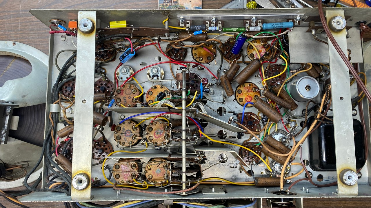
Once alignment was complete, I let the radio play at my bench for about half an hour or so. It seemed to be doing fine. Then began the process of carrying heavy items back upstairs and installing them in the radio’s cabinet. First the speaker was brought up and reinstalled, followed by the chassis itself.
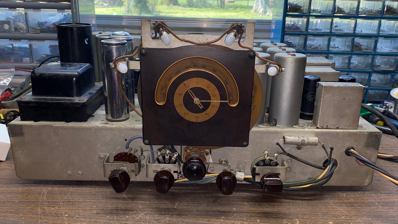
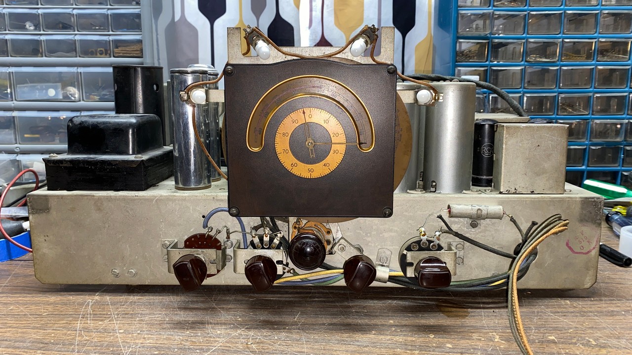
A look at the radio chassis before it was reinstalled in the cabinet.
Once I had the radio back together, I plugged it in, turned it on, and tuned in the signal from my SStran. I was dismayed to find that the SStran’s signal was still very weak and seemed to be coming and going.
I then tuned in the local Spanish station and let it play for a couple hours. This signal never wavered. The station cut power just before local sunset. I noticed the signal became weaker, but then this also did not waver or “come and go”.
I had noticed that when I put my SStran back on the air, that its signal would no longer reach our outside garage as it did in the past. This had led me to conclude that the RCA was fine – the problem was with the SStran itself.
What could cause an SStran’s signal strength to degrade from being unused for a couple years? This was puzzling to me. I did some experimenting with it after finishing up the RCA radio. I decided to return it it to the frequency to which I originally had it tuned – 660 kc, which is an open frequency in my area – and then carefully tuned it up using the procedure in the SStran manual.
After trying out a few different antenna choke settings, I found one which delivered the highest voltage as measured with my VTVM at the test points on the SStran designated for this purpose.
I then put the SStran back on the air, and connected the audio output of the laptop PC to it. After carefully setting the gain and modulation controls using a Philco 70 in the basement as a monitor, things seemed well. I then went back upstairs and turned the RCA C15-3 back on, and the signal seemed to be much better. In fact, as I type this, there has been no signal drop or other degradation. I guess my SStran prefers 660 kc to 890 kc; therefore, it shall remain at 660.
Meanwhile, the RCA C15-3 is now all tuned up and playing better than ever.