In the previous installment of this ongoing series, I had finished rebuilding what I am calling (for lack of a better term) the sub-base of the 37-116 RF unit. Now it is time to proceed with rebuilding one of the three subassemblies.
I decided to start with the antenna coil subassembly since it and the converter subassembly appear to be slightly less complicated than the oscillator subassembly. I am going to disassemble this to an extent which I have never done before, so I did not want to start with the hardest section. I want to get a feel for doing this.
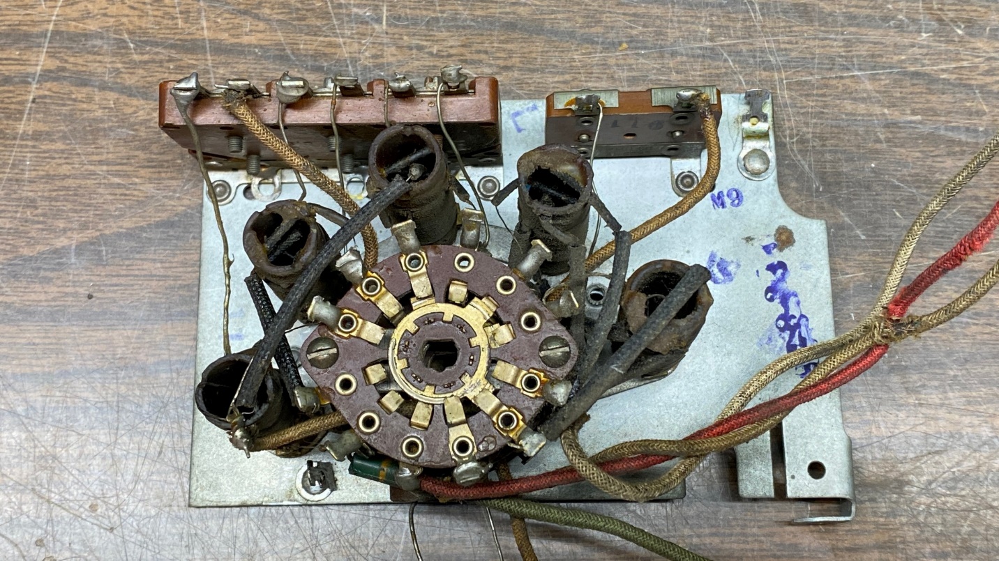
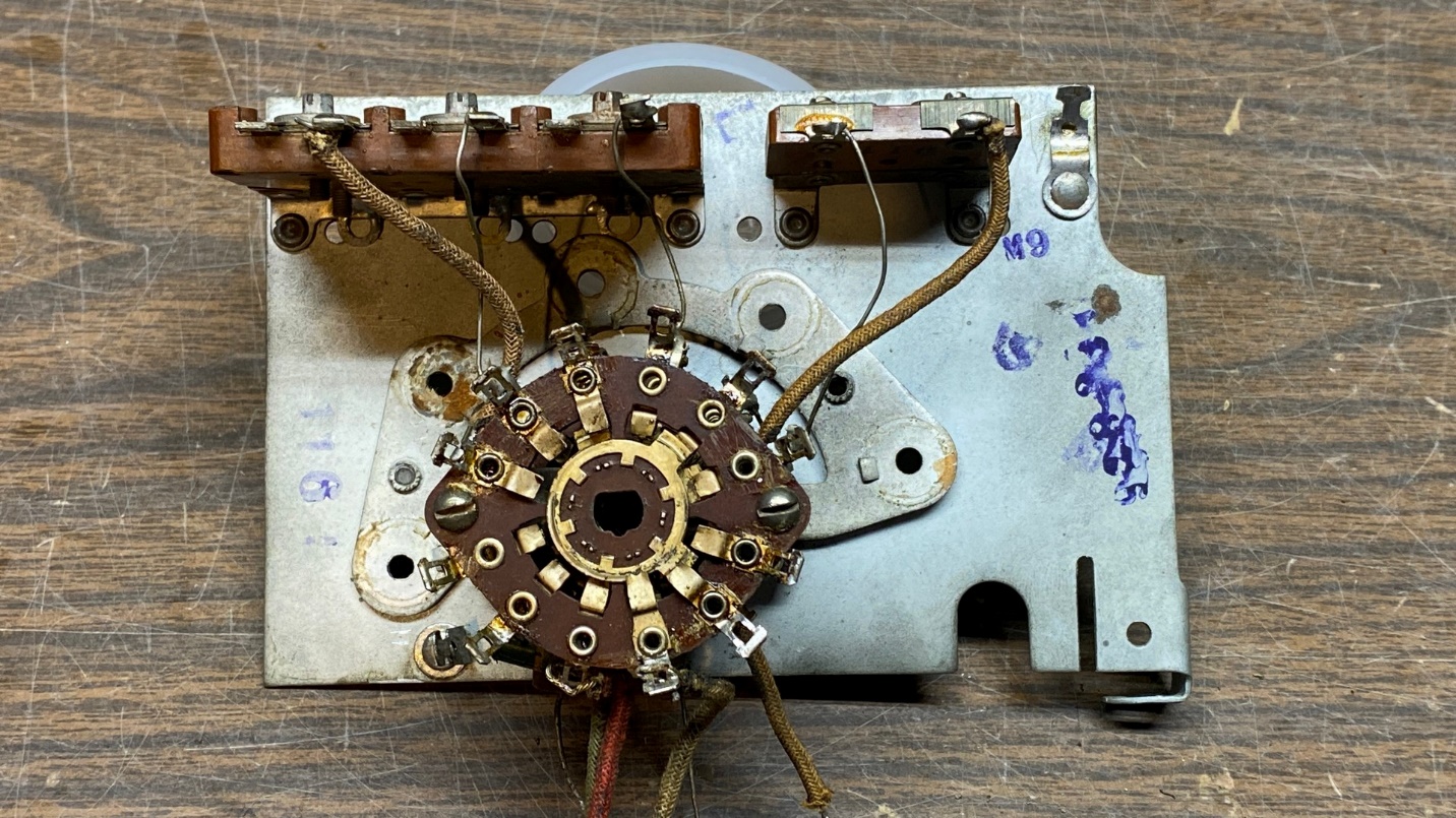
A look at the 37-116 antenna subassembly.
Now there is nothing left to do but to dive in…
There is nothing that appeared out of the ordinary in my initial inspection of the subassembly. It was typically dirty and dusty from having been around for 83 years.
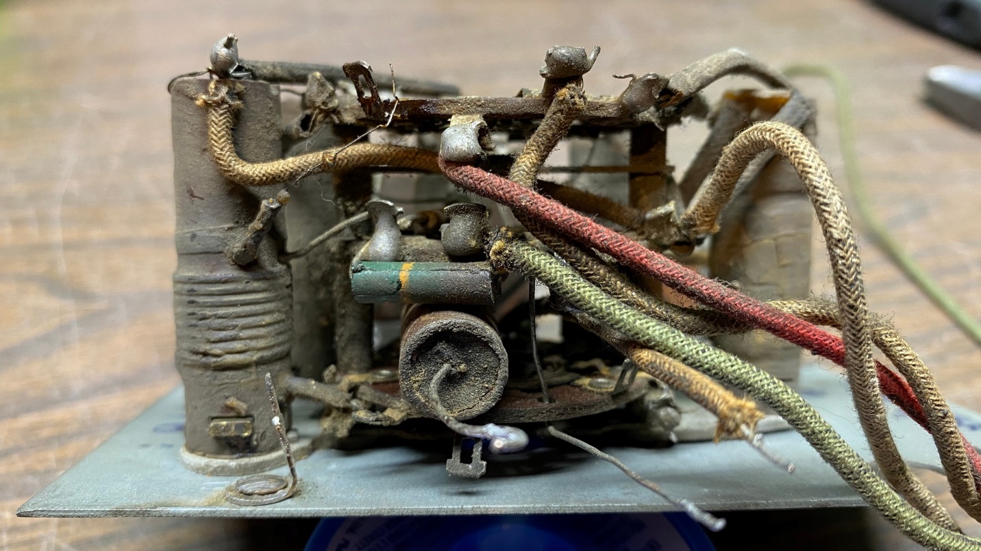
Another view of the same antenna subassembly.
Slowly, methodically and carefully, I began to remove each of the antenna coils from the switch/coil subassembly. Every lead wire of each coil, one coil at a time, was carefully unsoldered and when this was done, a tiny nut was removed from the bottom of the coil to allow the coil to be removed from the subassembly.
Removing coils from the subassembly
I first removed the band 5 antenna coil and slowly worked my way backwards by then removing the band 4 coil, then the band 3 coil, and so on, until finally all five coils had been carefully removed.
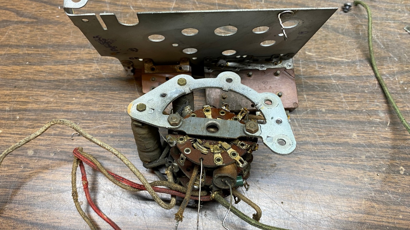
Band 1 and band 2 antenna coils removed from the subassembly
Through trial and error, I discovered that it was easier to remove the switch/coil subassembly (as shown in the photo above) in order to reach all of the terminals necessary to be unsoldered so that the coils could be removed. In fact, this is mandatory if you are going to go to the extremes as I have done here.
Remember, this is all new territory for me as well. I have never taken down an RF unit to this extent before. There is a good reason I am doing this which I will explain shortly.
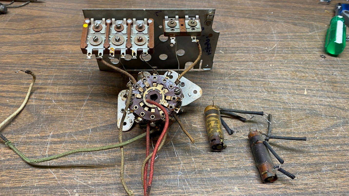
All the coils have now been removed.
Once I had removed all the coils, my next move was to unsolder the wires which attach to the various trimmer capacitors so that I can fully separate the switch assembly from this unit.
Starting to disassemble the switch assembly.
The switch wafer assembly is held onto a half-round metal plate by two nuts and lockwashers. The coils are also fastened to this half-round metal plate with one tiny bolt per coil. The entire unit is fastened to the subassembly with two bolts and lockwashers.
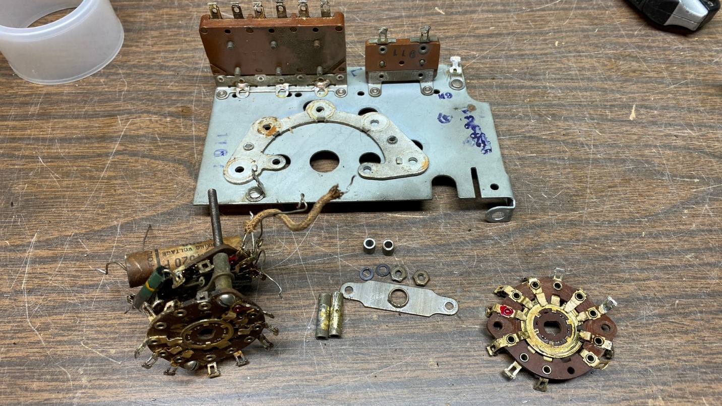
Once the switch wafer assembly was free of the half-round metal plate, it was now time to start separating those individual wafers.
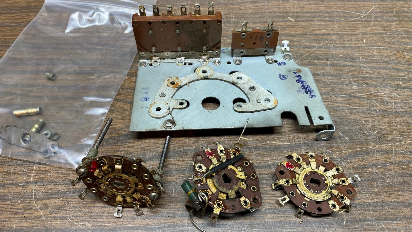
Here, all three switch wafers are now separated.
The long spacers between the bottom and middle wafer were actually threaded onto their respective screws and were somewhat difficult to remove. But I persisted, and ultimately triumphed.
There are also short spacers on these screws under the top wafer which are also threaded onto the screws. I left these in place, because there was no need to disassemble further once the three wafers had been separated.
If you look at the 37-116 schematic, you will notice that there are three sets of switch wafers in the antenna subassembly. These are labeled A, B and C in the 37-116 service information. Looking at the photo above, wafer A is at left; wafer B is in the middle and goes in the center of the assembly; and wafer C is at right and goes at the bottom of the assembly, nearest the half-round metal plate.
Notice also there are red dots on each of the wafers, over one terminal on each wafer. This is red nail polish which I applied. This serves two purposes: it shows which terminal of each wafer is terminal 1, and also indicates which side goes “up” when the wafers are reassembled.
I had previously mentioned that I had a reason for disassembling this unit in such a manner. The reason is this: Disassembly allows me to inspect each switch wafer carefully for any signs of carbon tracks, and to carefully clean each wafer which is not possible to do when everything is assembled. While doing this, I have also discovered that disassembly makes it easier to replace any resistors (there is one) and paper capacitors (likewise, one) than it is when everything is assembled.
Now comes the big question:
Can I ever get it all back together again?
Stay tuned to find out!
To be continued…