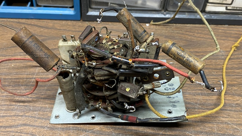
The messy maze of wires, capacitors, and other things you see in this first photo is the oscillator section of the Philco 37-116 RF unit. It is the most complicated portion of the RF unit, and so you can see why I saved this for last as I did not look forward to getting started on rebuilding this section.
Before I did anything, I sat down and documented another key or “road map” showing how things interconnect between the final four switch wafers. As you will see below, things are considerably more complicated, mainly because of the “Magnetic Tuning” used in these high end Philco models.
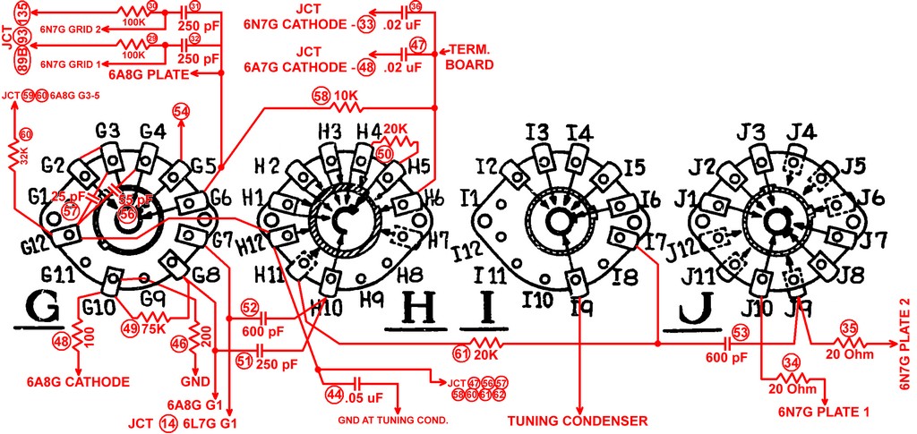
Drawing which shows the various connections to, and within, the oscillator section switch wafers.
This shows all the capacitors, resistors and wires which connect to, and within, these four switch wafers of the oscillator section. It does not show the wires which connect from switch wafers to the trimmer condenser assembly; the schematic, plus the illustration of the trimmer condenser assembly, should suffice for these wires.
The other keys or “road maps”, including the partial schematic and the illustration of the trimmer condenser assemblies, may be found in Part 4 of this series.

Another look at the oscillator section before disassembly.
Once the multitude of capacitors, resistors and wires were removed from the switch assembly, it looked much like the others, only having an extra switch wafer on top. As before, it is important to take your time and make sure you have fully documented everything, as I have tried to do here and in Part 4 of this series.
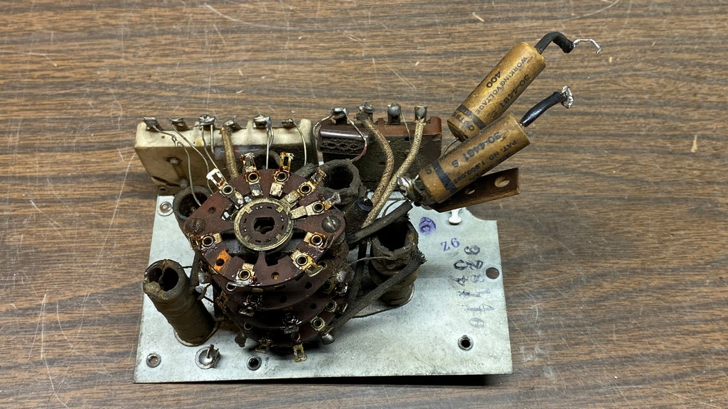
After removal of many of the capacitors and wires, mostly from switch wafer G (top).
Before I could remove all the paper capacitors, though, I had to remove the Band 1 oscillator coil just so I could have access to the switch wafer terminal to which the final two paper capacitors were attached (see photos above and below).
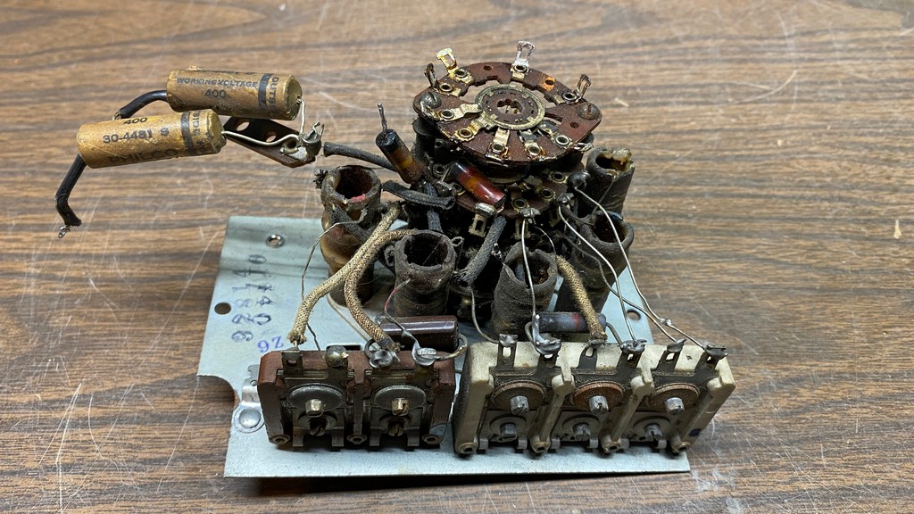
Another view of the oscillator section after removal of parts and wires had begun.
Once that was done, I removed those last two paper capacitors, and then proceeded to remove the remaining four coils and the last couple of resistors from the switch assembly.
The coil wires in this section were much more difficult to remove than were the coil leads in the previous two sections. Whoever assembled this section back in mid-late 1936 or early 1937 took great pains to wrap the coil leads around the switch terminals multiple times, which made disassembly much more difficult. But I managed to remove all five coils without breaking any coils leads.
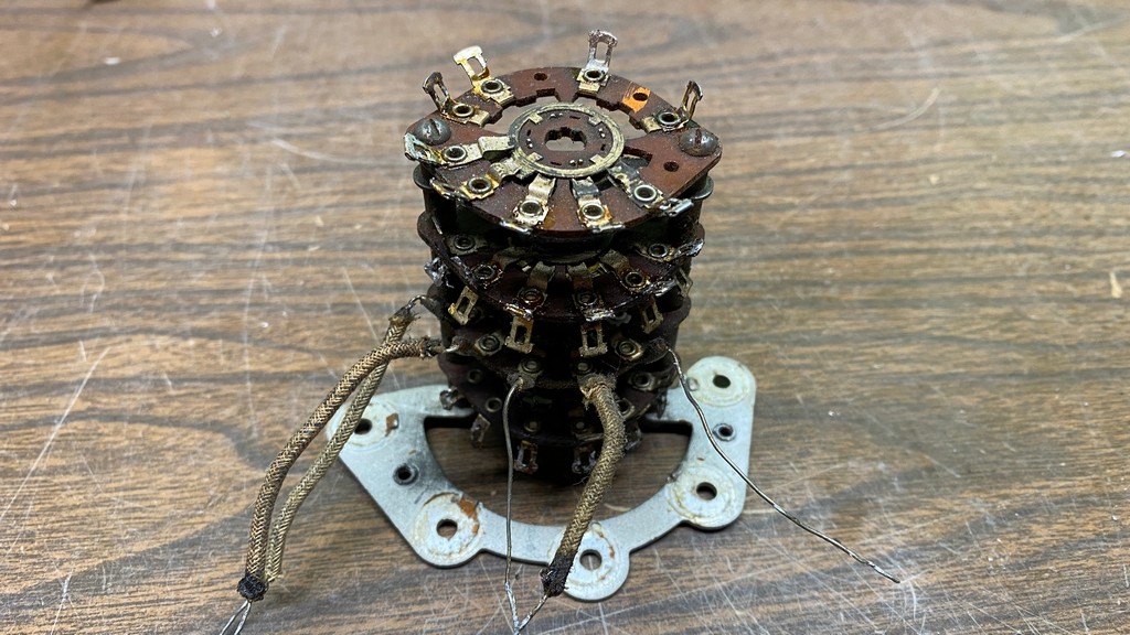
The mostly bare oscillator switch assembly after removal of everything including the five coils. A few wires remain to be removed.
Once the coils were removed and put into a safe place out of the reach of cats, the switch assembly looked as it does in the photo above. As you can see, there are still a few wires which need to be removed before I disassemble this assembly so that each individual wafer may be cleaned.
By now it was Saturday afternoon, December 5. As I had another chemo session on Monday, December 7, I chose here as a stopping point for now.
Next time…disassembly and cleaning of the switch wafers, followed by reassembly of everything.