Last time, I spent the entire article attempting to describe my method of restuffing aluminum electrolytic capacitor cans of the 1930s. With that out of the way, now let’s get back into the actual restoration of this radio.
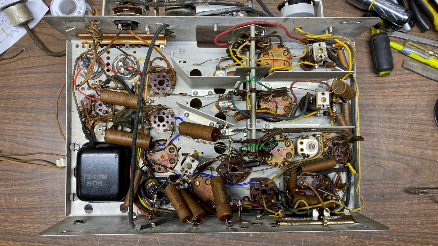
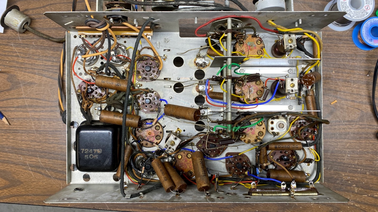
How the chassis looks underneath with roughly half of its capacitors restuffed. Some new resistors and a few new wires have also been installed.
After I restuffed both electrolytic capacitor cans, I reinstalled them on the chassis.
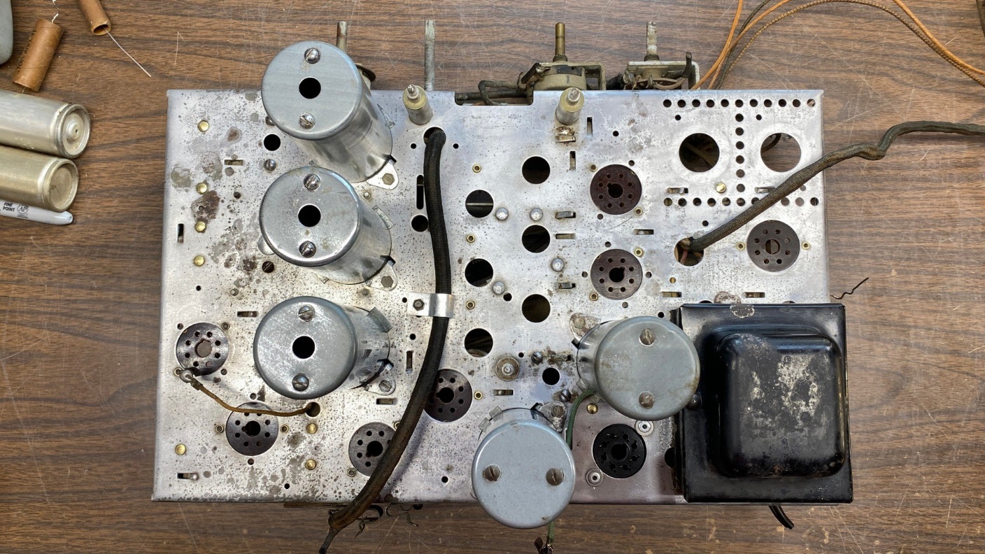
I had previously removed all the paper capacitors as seen on the left side of the chassis (see photo above). While I was at it, I also removed the resistors on the same side, as well as some rubber-covered wires. The insulation of the wires had deteriorated to the point they were no longer safe to use.
I would not have gone to such extremes unless I had something to help me put the wires and components back into place properly. Fortunately, RCA published such a document along with the service information for this radio. You see, up until 1937, RCA radio documentation was very comprehensive and included not only a schematic, but also a wiring diagram. It was this wiring diagram which gave me the confidence to simply remove wires and parts en masse, knowing I would be able to replicate the wiring later on with the aid of the wiring diagram.
You may see a copy of the wiring diagram for the T9-10, included as part of the service data for this radio here:
RCA_T9-10-C9-4_LateOnce I had restuffed the paper capacitors which I had removed from the left side of the chassis, I began to reinstall everything on that side beginning with the new PVC insulated wires to replace the old rubber-covered wires. After the new wiring was in place, the new resistors and restuffed paper capacitors were installed.
With that portion of the radio finished, it was time to turn to the right side of the chassis.
Here, I have begun to remove the remaining paper capacitors and old resistors from the right side of the chassis.
The right side of the chassis contained more capacitors, more resistors, and more rubber-covered wiring which needed to be removed. In addition, I also removed the shields separating the sections of the band switch in order to have better access to the terminals in that area where components and wiring needed to be removed and replaced.
Once I had removed everything on the right side of the chassis, it looked as pictured below.
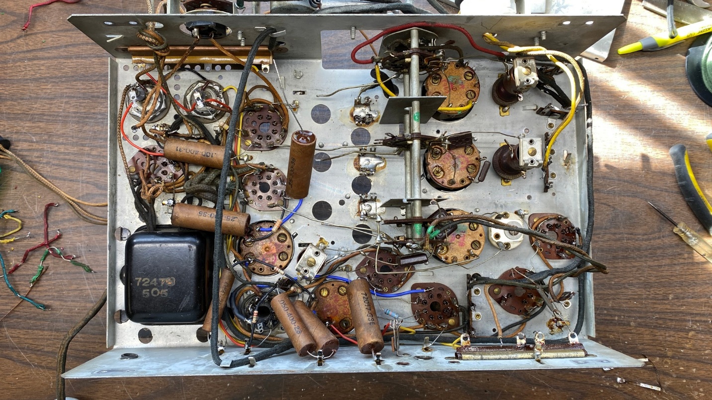
This is how the chassis looks with all paper capacitors, resistors, and rubber-covered wires removed. The shields in the center of the chassis, adjacent to the sections of the band switch, were also removed to gain access to several key components.
With the RCA wiring diagram as well as previous photos I had taken of the underside of the chassis, I was able to replace the old rubber-covered wiring as well as install new resistors and the restuffed paper capacitors.
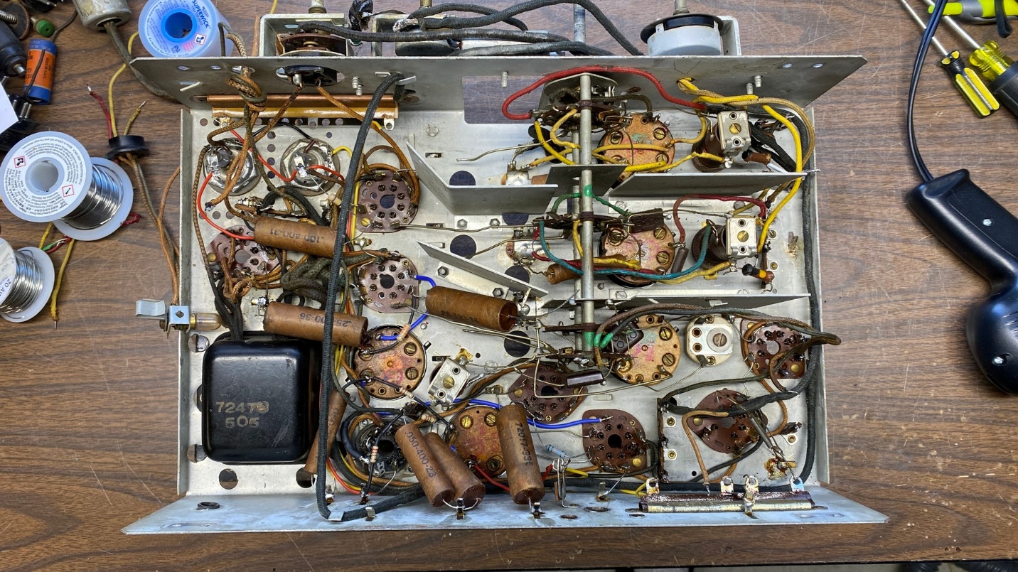
After working on the set for a few days, off and on, it looked as shown below.
Rubber-covered wiring and old resistors were now replaced on the right side of the chassis. The paper capacitors were gutted, restuffed with new components, and reinstalled in the chassis.
I decided this would be an appropriate time to replace the speaker wiring as well as the wires which go to the dial lamps.
Many RCA speaker cables of this period have a three-pin jack as shown below.
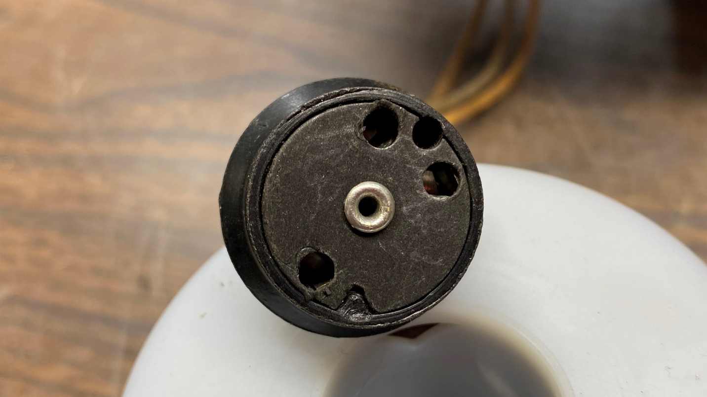
A typical mid-1930s RCA speaker jack.
Notice the rivet in the center. Sometimes, you can simply pull this out with a pair of needle-nose pliers. Other times, the rivet is firmly in place and must be drilled out.
This time, I was lucky and the rivet was easily pulled out, allowing me to remove the fiber cover and reach the connections inside.
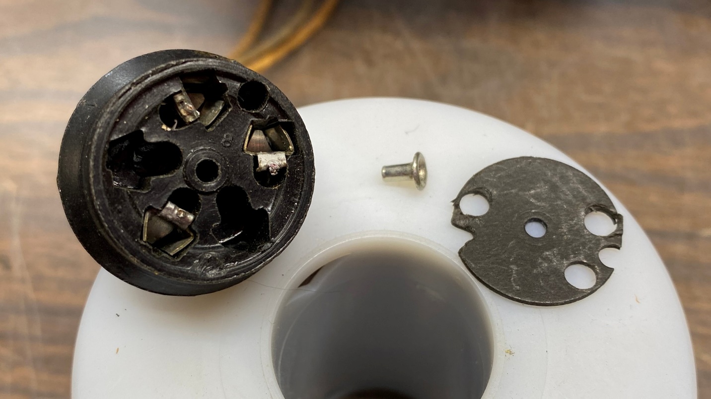
A disassembled speaker jack.
Notice there are three metal connectors inside the jack, which correspond to the pins of the speaker plug which is attached to the back of the speaker. Each connector may be carefully pulled out of the jack by careful use of needle-nose pliers.
Pull these out one at a time. Unsolder and remove the old wire. Then push the new wire through the hole in the back of the bakelite jack, solder the new wire to the connector, and then push the connector back in place.
Repeat this for the other two connectors.
When finished, put the fiber insulator back in place and reinstall the rivet. You may have to use a tiny dot of epoxy to hold the rivet in place.
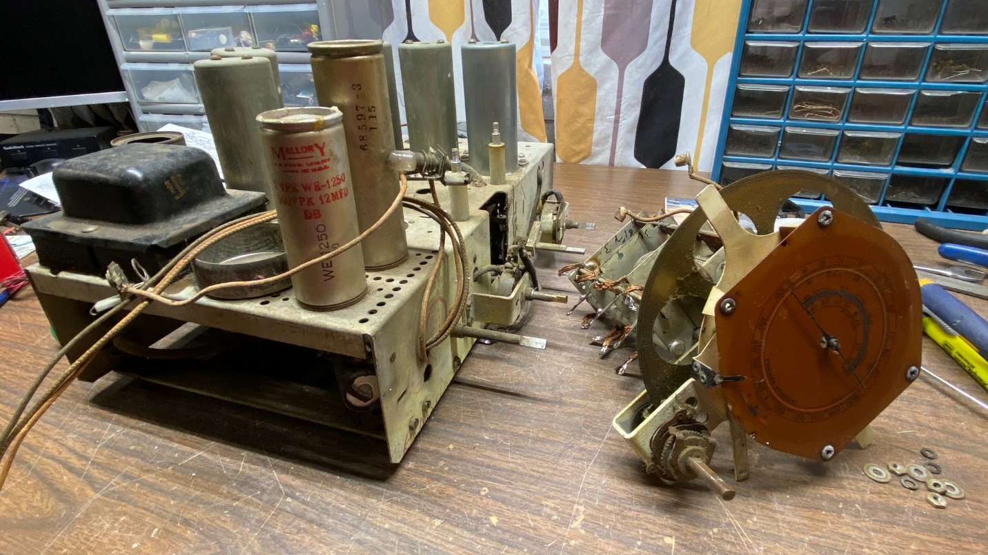
With that chore out of the way, it was now time to remove the good tuning condenser from the parts chassis.
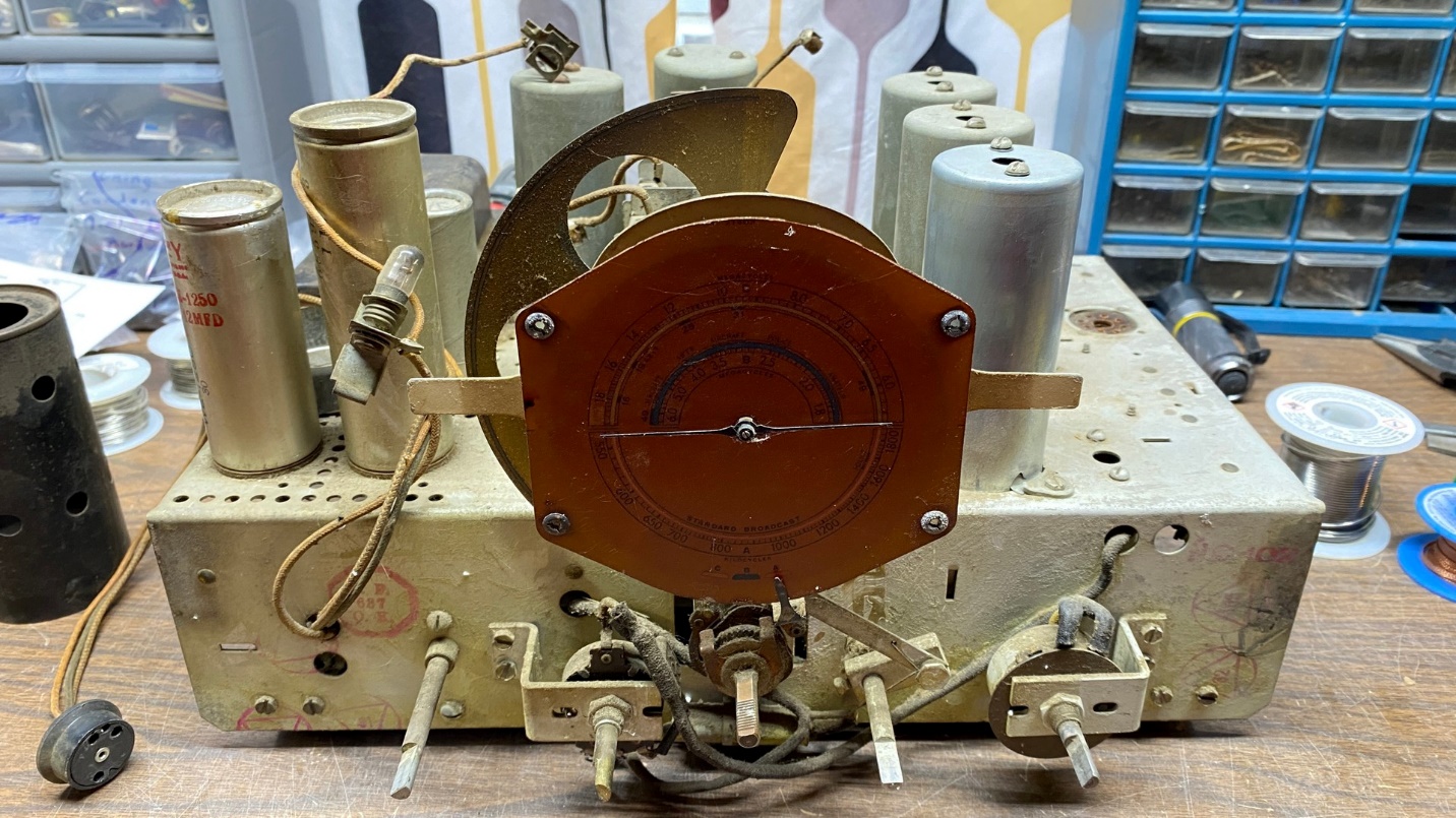
The T8-14 parts chassis is placed on the bench so I may remove its tuning condenser.
The procedure to remove this tuning condenser was identical to the removal of the T9-10 tuning condenser. Three stator wires and four copper braids must be unsoldered from underneath the chassis, plus four more copper braids on top of the chassis. The dial lamps need to be pulled off the dial assembly. The mechanism which actuates the band indicator pointer must be removed from the band switch.
Finally, three nuts, lockwashers, and flat washers are removed from the top of the chassis after which the tuning condenser may be removed from the chassis.
The T8-14 tuning condenser removed from its original chassis.
Installation on the T9-10 chassis was the opposite of removal from the T8-14 chassis, and soon, I had the donor tuning condenser installed on the chassis as seen below. (Yes, I remembered to replace the rubber bushings.)
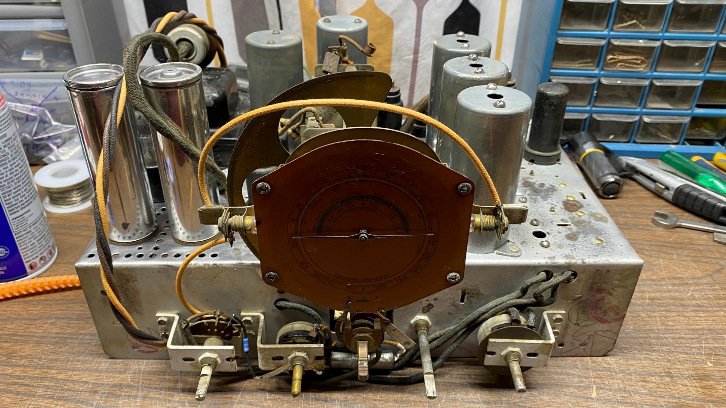
The T8-14 tuning condenser is now installed on the T9-10 chassis.
The chassis was getting close to the point where it could be tried out for the first time. However, a little more work needed to be done. We’re out of room again, so I shall have to continue the saga in the next installment. Please join me then.