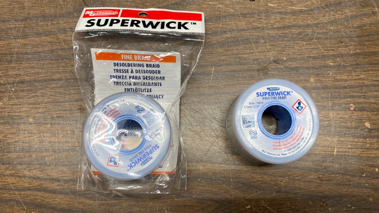
I had run out of desoldering wick, so I had to order more from one of my favorite parts suppliers, Mouser Electronics. This time, I ordered two 100 foot rolls of wick instead of the usual one, so I would have plenty to last a while.
This stuff is expensive! You’re looking at over $100 worth of desoldering wick in the photo above. Hmmm…maybe a desoldering station would have been a good idea after all.
In any event, it was time to continue work on this Philco 90 chassis.
I knew I needed to remove the tuning condenser from the chassis so I could clean the chassis. So, I proceeded to do this.
The tuning condenser has no less than seven leads, plus the two leads for the dial lamp; all of these had to be unsoldered and removed before I could remove the part from the chassis. I unsoldered the two dial lamp leads at the dial lamp socket; the other leads were unsoldered under the chassis.
I made a crude drawing to assist in reconnecting the wires when I was finished:
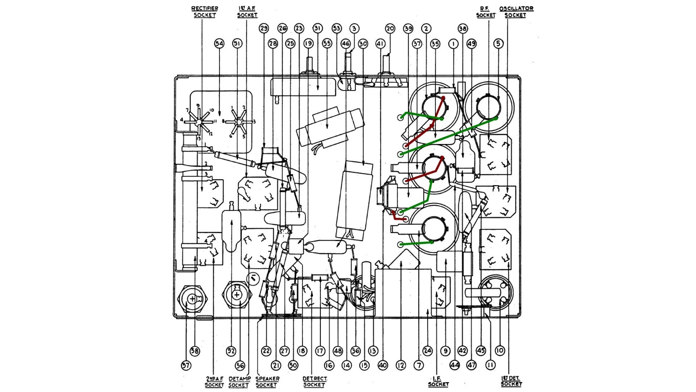
A drawing showing wire connections for the tuning condenser. Stator wires are shown in green, rotor (tuning condenser frame) wires in brown.
Once all wires were disconnected, the three tuning condenser mounting bolts were then removed from under the chassis. Following this, the condenser itself was finally free of the chassis as seen below.
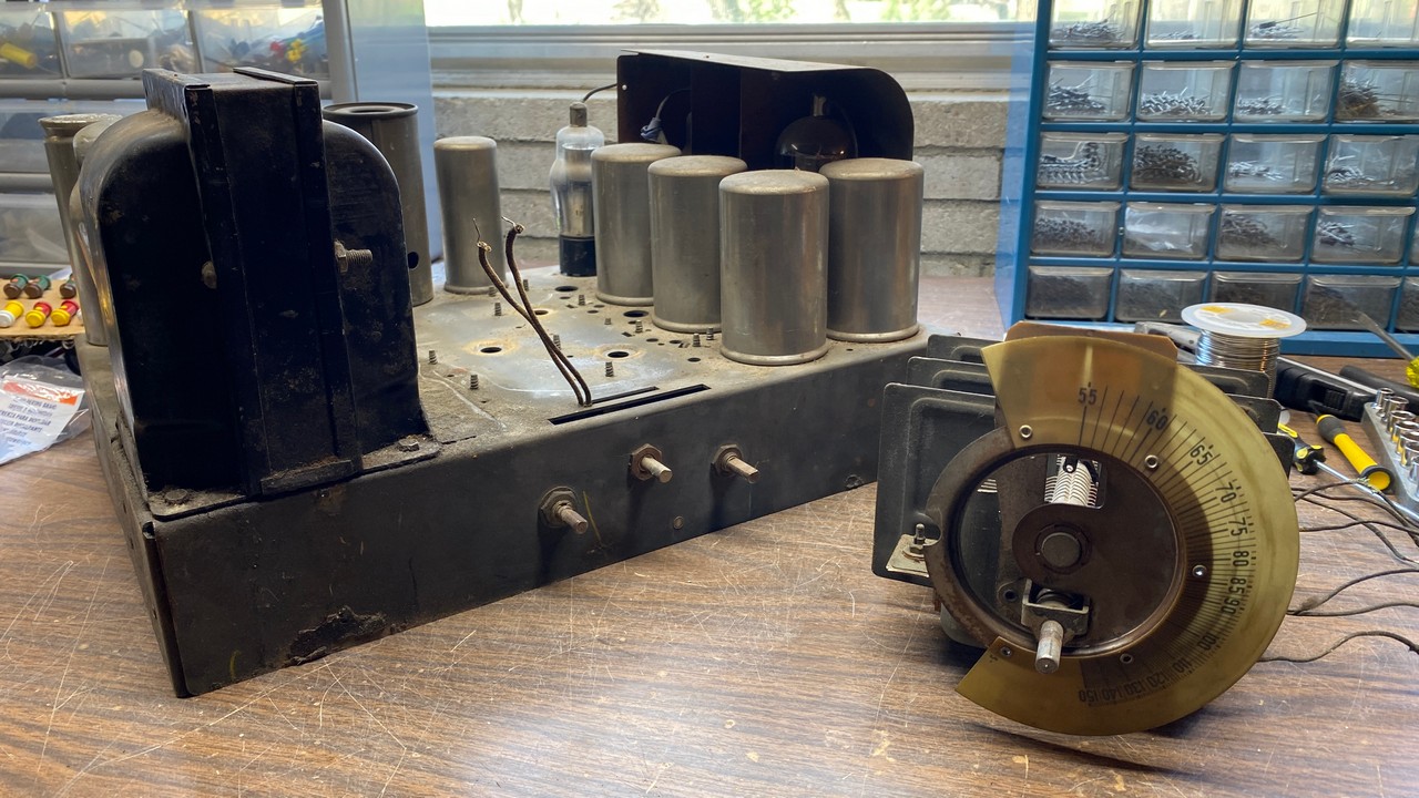
The Philco 90 tuning condenser has now been removed from the chassis.
Taking an idea from my friend Steve Davis as he was in the process of restoring his Philco model 118, I decided to try lacquer thinner to clean up the chassis. We had begun to have unusually warm temperatures in mid-April, so I took advantage of the good weather and set up operations outdoors in order to perform the cleaning procedure.
I soon found that lacquer thinner did indeed do a good job of cleaning dirt and grime from the chassis surface, but did nothing to remove the black waxy substance that lad leaked out of the set’s power transformer. Therefore, I switched to mineral spirits. This took some scrubbing, but it did remove all traces of wax from the chassis.
The end result may be seen below.
The cleaned up Philco 90 chassis.
You will notice some surface rust remains. I knew the cleaning process would do nothing for these spots. I decided to leave them as “character marks”.
I let the chassis remain outside for a few hours so the chemical fumes could dissipate. That evening, I returned the chassis to my basement workbench.
Now that I had desoldering wick, I decided it was time to continue rebuilding fixed capacitors. I realized that I was completely out of 0.1 uF capacitors, so I had to place another Mouser order.
While I waited for these, I decided to move on to the two metal can capacitors located under the chassis.
Here, it should be noted that the factory service bulletin contains an error. One of the cans actually contains three 0.25 uF capacitors while the other has three capacitors of various sizes – 0.1, 0.25, and 1.0 uF. This error is documented here on the Philcoradio.com website.
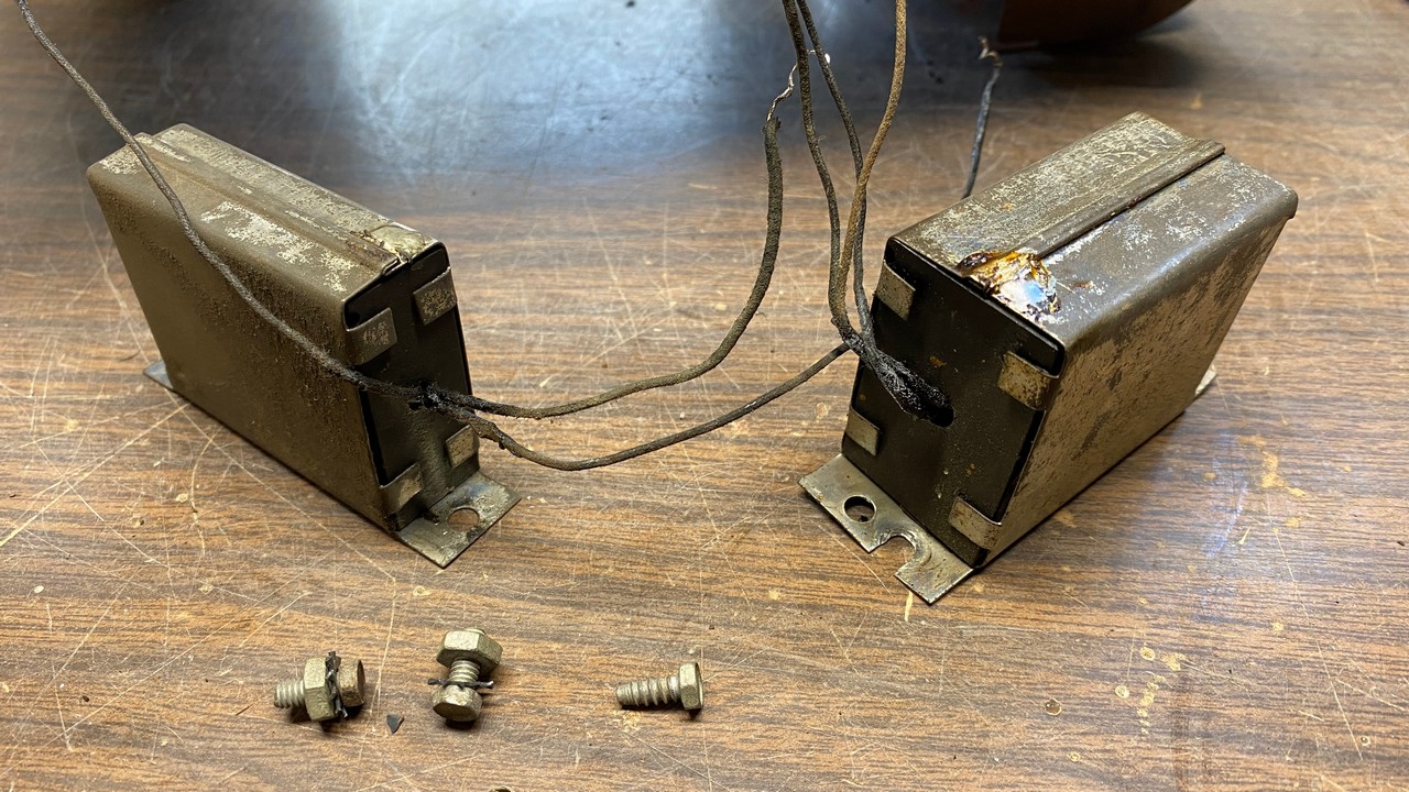
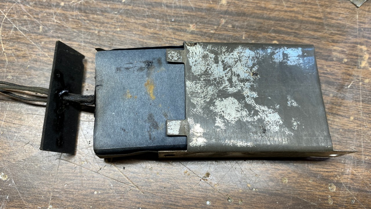
Parts (24) and (30), as removed from the radio chassis.
These cans are usually very easy to rebuild. The old capacitors were encased in a black tarry wax, wrapped with fish paper, and shoved into a metal can with a thick piece of fiber in each end. Normally, one only needs to fold open the four tabs on the end from which the wires protrude, and then gently push on the fiber which is exposed on the opposite end to remove the “guts”.
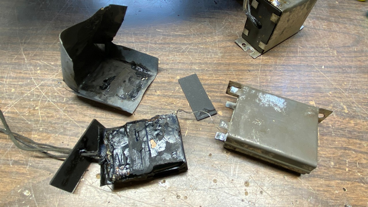
Part (24), which contains three 0.25 uF capacitors, is carefully taken apart.
Once the part is out of the can, the old fish paper is carefully unfolded and peeled away from the tarry capacitor assembly. Now, I carefully pull each wire connection off the assembly. If you are careful the wire as well as the soldered connection will easily pull free of the assembly.
The disassembled part (24).
I then carefully scrape away any remaining tarry wax from the wire connections, and unsolder each wire from the thin metal tab it is soldered to. You could use new wires on your new capacitors if you wanted to. However, when possible, I like to reuse the original wires for the sake of appearance.
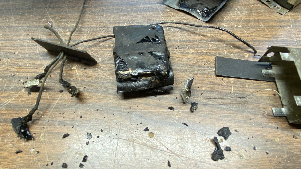
All connecting wires have been pulled free from the old capacitor assembly.
Please note that there is a thin bare wire, one end of which is soldered to the capacitor can. If you work carefully, you may reuse this wire as well.
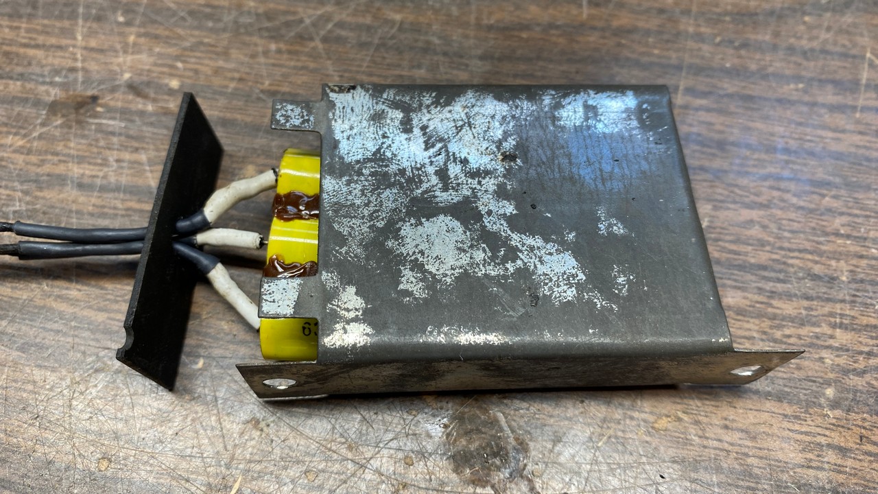
Next, I prepared three 0.22 uF, 630 volt capacitors. (0.22 uF is the modern standard value which is commonly used to replace 0.25 uF capacitors.) Using another trick I learned from reading Steve Davis’ restoration of his Philco 118, I used some hot glue to hold the three capacitors together.
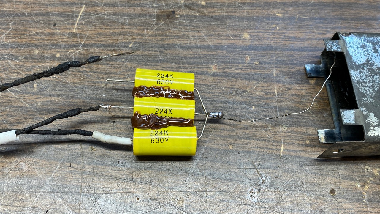
Hot glue was used to hold the three 0.22 uF capacitors together.
I twisted the leads of one end of the group of three new capacitors before applying the hot glue. Although these yellow film capacitors are somewhat fragile and will be destroyed if touched with a hot soldering iron or gun, hot glue does not harm these capacitors.
I then soldered the old leads to the leads of the new group of capacitors. Notice how the bare wire was soldered to the common point of three capacitors, while the three insulated wires were soldered to the other free ends of the capacitors. Each joint was insulated with heat shrink tubing to ensure the three connections would not accidentally short together.
The three original insulated wires had compromised insulation at the end where they would go though the hole in the fiber end, so I decided to add more heat shrink to each wire, knowing it would be visible. However, I felt that it was necessary to, again, prevent these wires from possibly shorting together.
When the wires were soldered in place and insulated with heat shrink tubing, the assembly was put back into the metal can. I first place the fiber sheet which was in the opposite end into the can, and the slip the old fish paper back into the can to further protect the new capacitors. You can encapsulate these capacitors with hot glue if you wish. However, these three took up much of the empty space inside the can (and fish paper), so I did not bother to add more hot glue to these.
The new capacitors are placed inside the old metal can.
The wires are run through the hole in the fiber end. The fiber is then placed over the end of the can and the four tabs are then folded over to hold everything in place. Part (24) was now rebuilt.
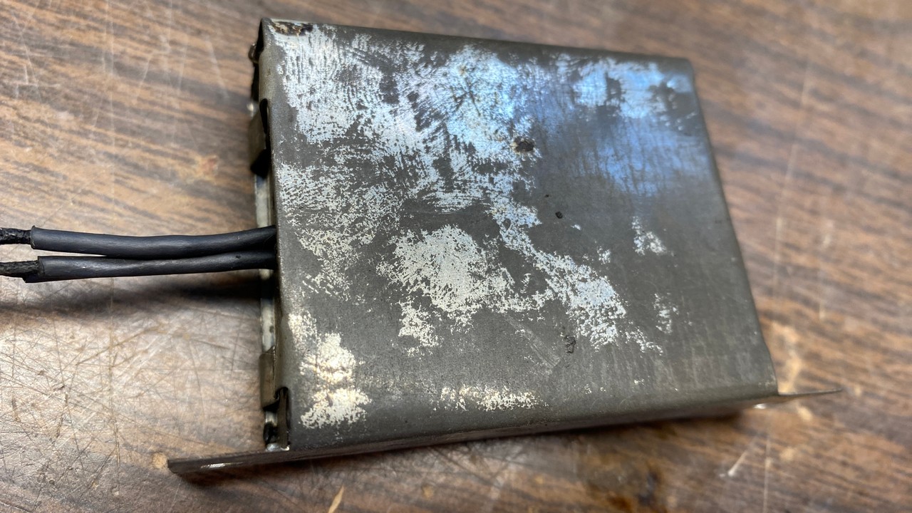
The rebuilt part (24). Other than the heatshrink tubing on the wires, it retains its original appearance.
I see we are out of space again, so I will continue the saga of the Philco 90 next time. Until then!