Nearly three weeks after I had sent the field coil off to be rewound, I finally heard from the rewinders, letting me know the coil was finished. I paid the bill and had it back here three days later.
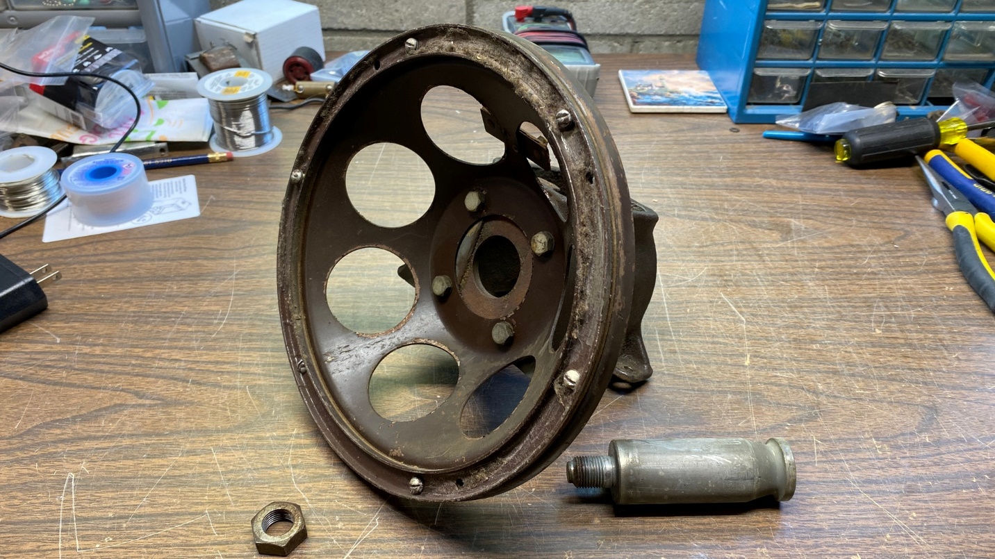
So now it was time to pull the speaker frame back out and get it ready for the installation of the new field coil, along with the new audio output transformer I had purchased in the interim.
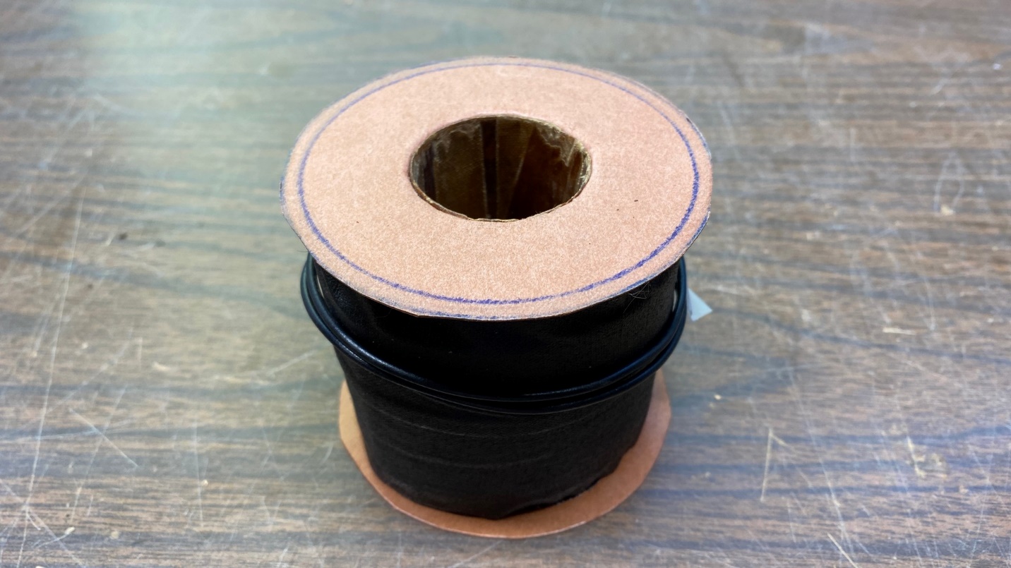
The new field coil.
It is not quite correct to call the field coil “rewound”, since it consists of all new magnet wire wound on a new bobbin.
I removed the pole piece and the two round fiber spacers from the speaker frame. The new field coil was the same size as the original, measured 3275 ohms as per original specs, and fit nicely in the original speaker “pot” as shown below.
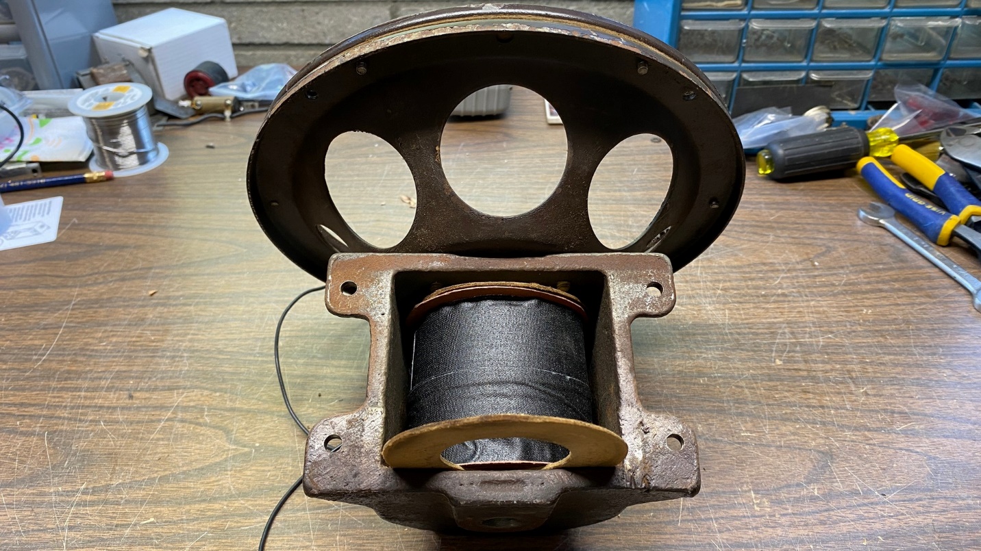
The field coil is now in place in the speaker “pot”. One of the original fiber spacers is in place at the front end of the coil, and the rear spacer is being put into place.
Once the new coil and spacers were in place, the pole piece was reinserted, and its nut at the back of the “pot” was retightened. This required me to reattach the metal piece which holds the speaker inside the speaker cabinet, and clamp that to a table once again so I could adequately tighten the nut.
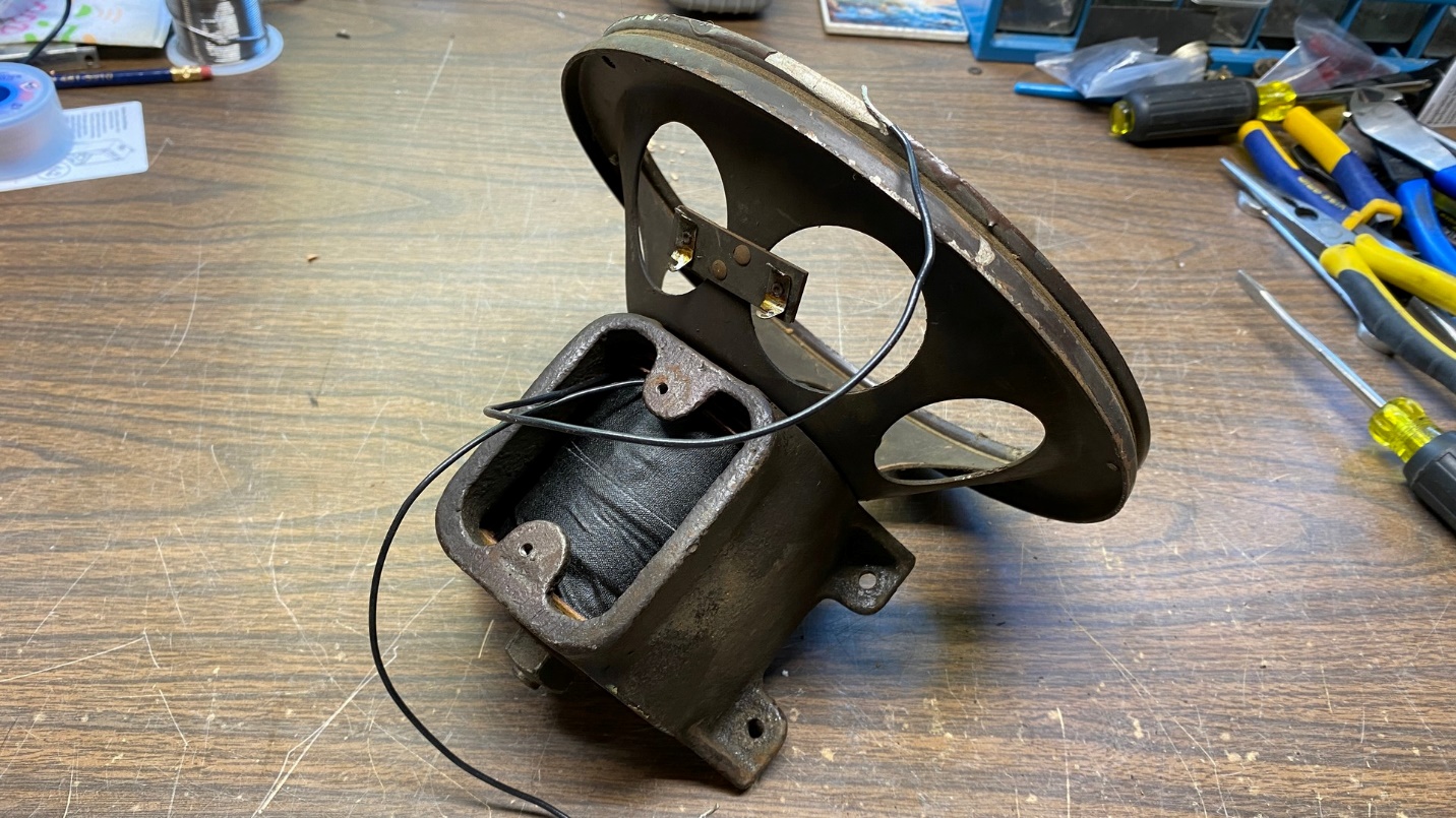
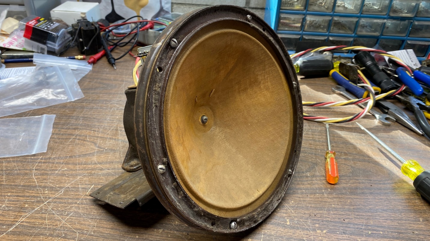
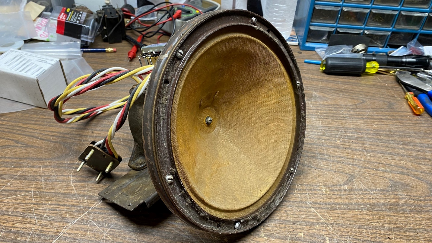
The speaker with field coil and pole piece reinstalled. The wires of the field coil are protruding from the top as they should.
Now it was time to begin rewiring everything, and to get out that new audio output transformer.
As you can see below, I chose a Hammond 125C universal push-pull transformer.
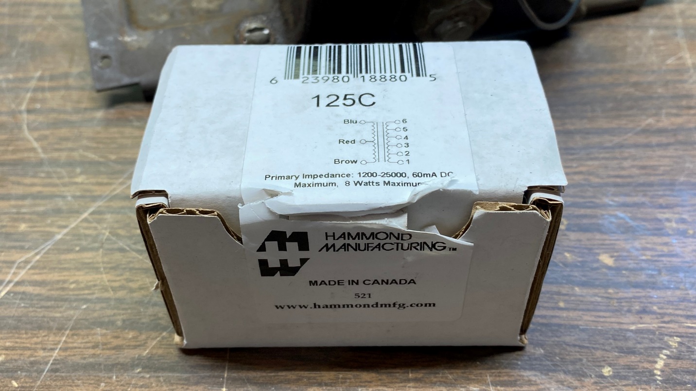
New Hammond audio output transformer, ready to be attached to the speaker.
As you may recall from Part 1 of this series, I had previously constructed a new speaker cable for this speaker, using the original four-pin plug (which I repaired) and cloth-covered, 600 volt rated, 20 gauge wires.
I began connecting wires from that new speaker cable first to the output transformer, and then to the leads of the new field coil. Before long, every wire was soldered in place and double insulated with two layers of heat shrink tubing.
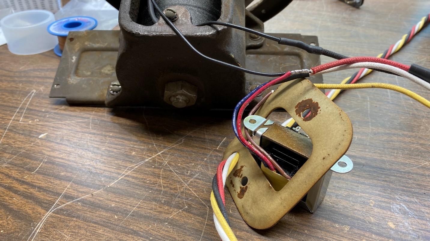
The new speaker cable is attached to the new output transformer and field coil.
I thought about attempting to conceal the new audio transformer inside the old shell but decided against it for two reasons. One, the six output terminals would be difficult to keep from touching the metal shell; and two, the entire assembly will be inside its decorative metal cabinet when it is all finished, so the new transformer will not normally be seen.
Once I had every lead of the new speaker cable properly connected to every lead of the new field coil and transformer, I mounted the new transformer on top of the “pot”, where the old transformer had been mounted.
A short length of large diameter heat shrink tubing, placed over the end of the speaker cable, now serves as a sort of makeshift strain relief and is large enough to prevent the cable from being pulled out of the hole in the fiber insulator through which it passes.
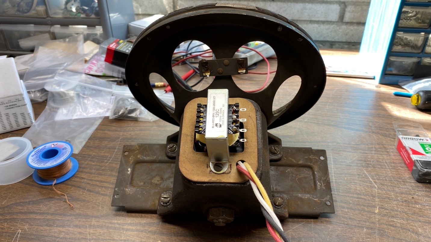
The speaker now has a new field coil, new audio output transformer, and new cable.
With that part of the assembly finished, it was now time to reinstall the cone and voice coil.
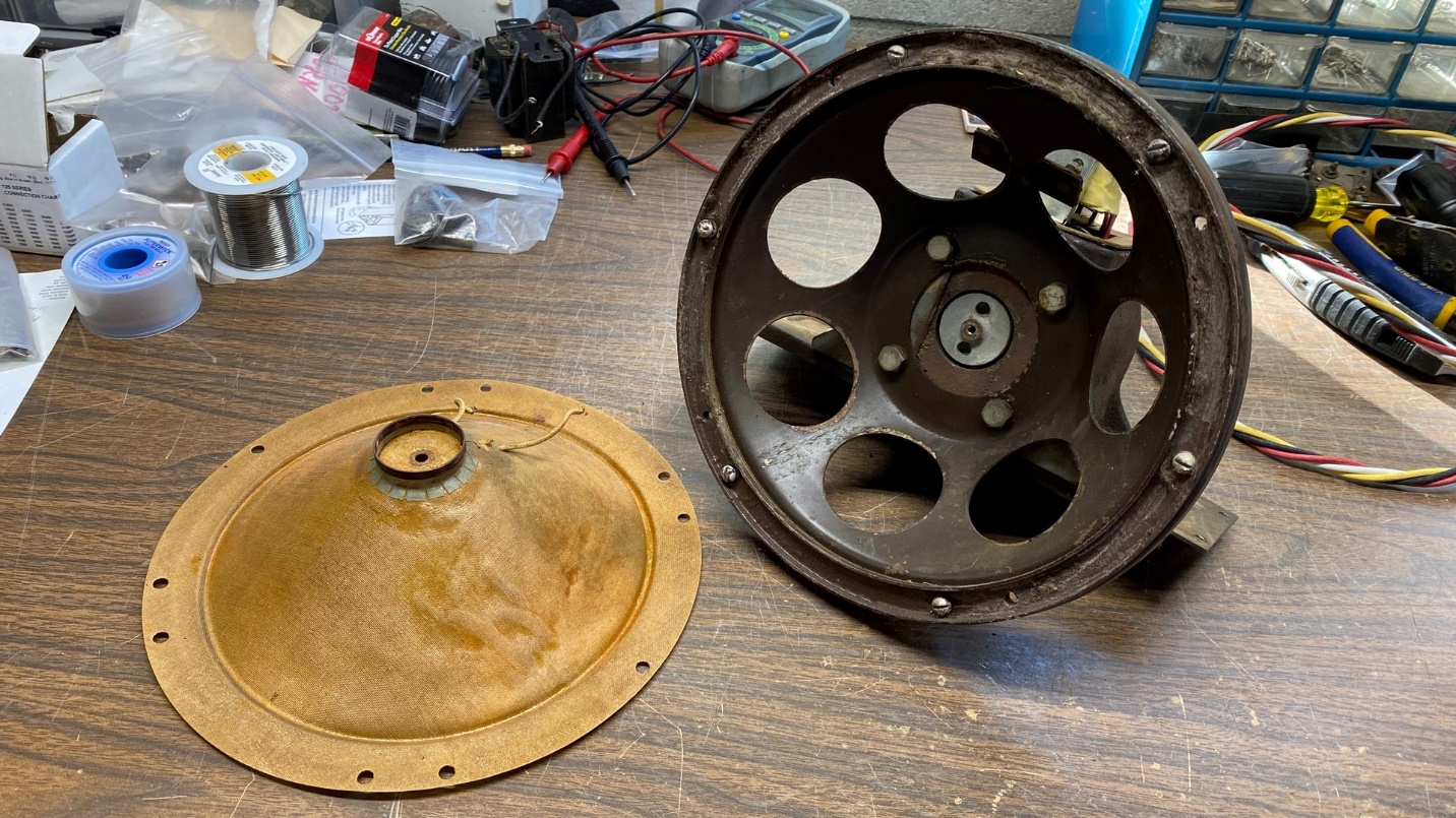
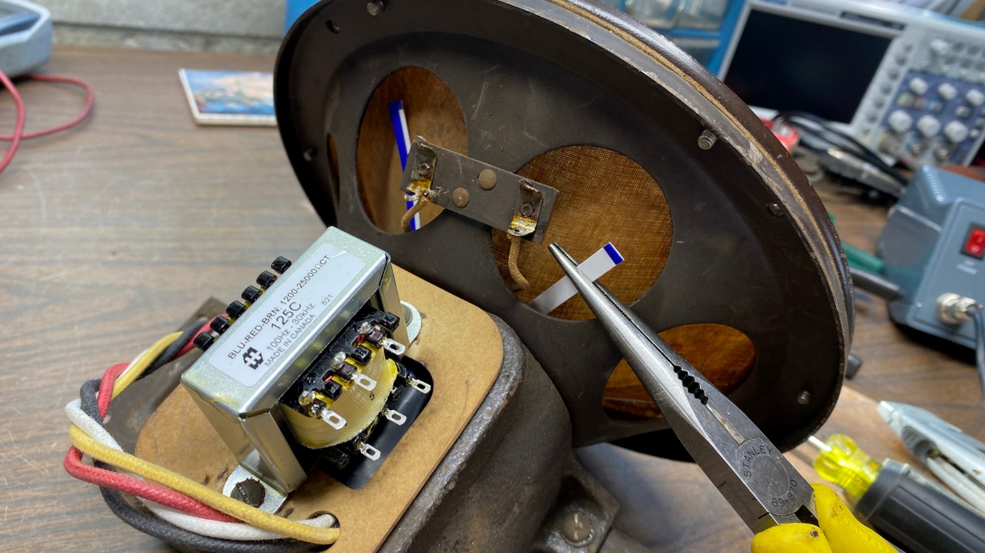
Cone/voice coil assembly ready to be reinstalled on the speaker.
I cut four slim but long shims from a package which was about the thickness of a business card, and placed these shims inside the voice coil gap, evenly spaced around the gap. The purpose of these shims was to re-center the voice coil so that it would not rub when the speaker is in operation.
I also removed the trim ring so the cone could be reinstalled.
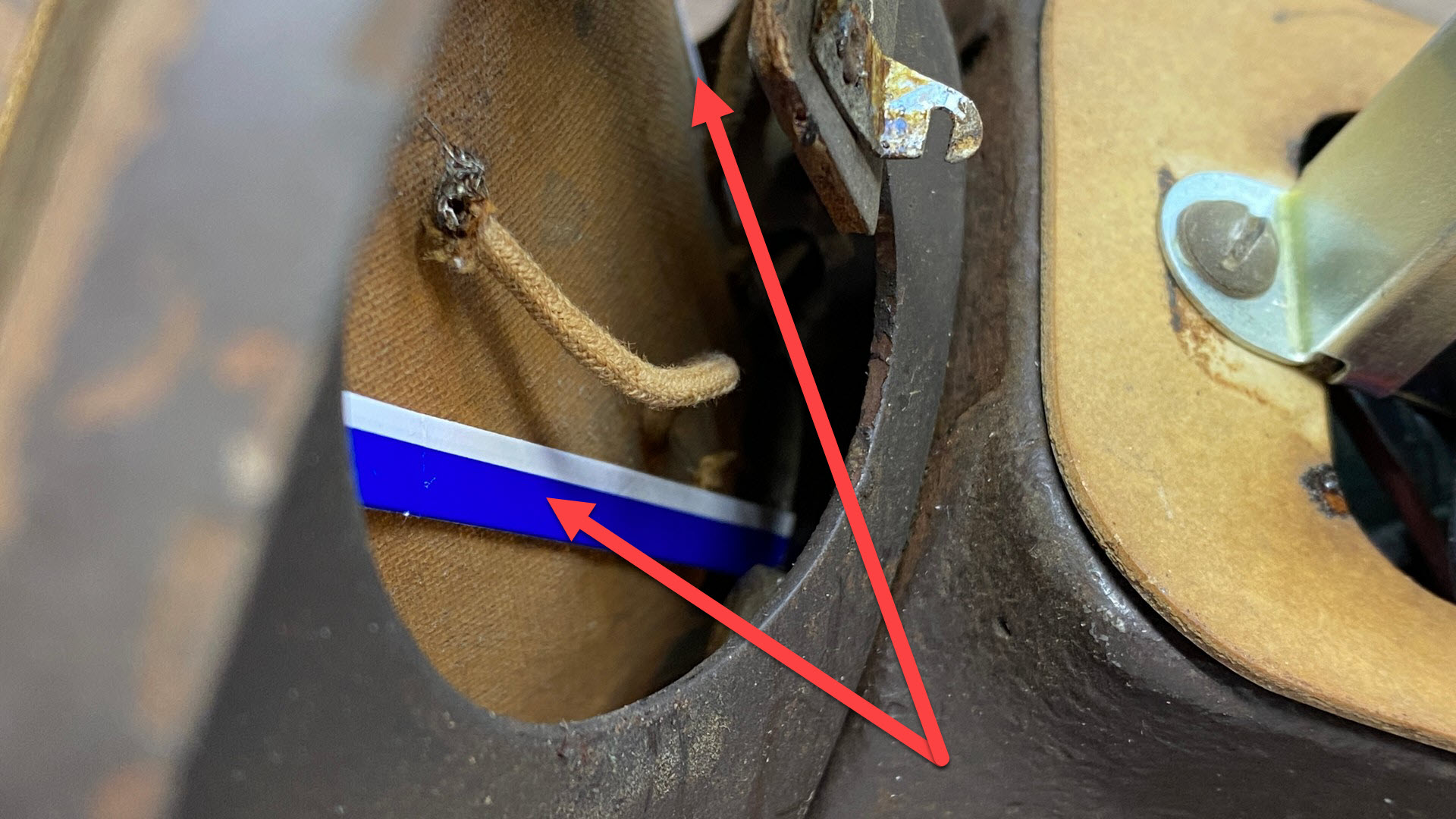
The arrows point to two of the four shims used to re-center the voice coil.
Once the shims were in place, I carefully placed the speaker cone and voice coil on the front of the speaker, gently pressing the voice coil into the gap in such a manner that the shims would be behind the cone as shown above. I continued to gently press the voice coil into place until it was against the screw hole on the pole piece. Making sure the cone was properly placed on the frame so that all the holes in the cone matched all the holes in the frame, with the voice coil leads at the top of the cone, I put the trim ring back in place and began reinstalling the mounting screws, beginning with the flatwasher, lockwasher, and screw at the center of the spider which screws into the center of the pole piece.
The screws holding the spider (center of cone) and the trim ring are now back in place.
Starting with the center screw, I began to carefully tighten each one. You must be careful doing this, especially with the center screw as one slip could destroy the cone, spider, and/or voice coil.
Removing the shims after the screws were tightened.
Once all the screws were tightened, I began to carefully pull out the shims. I took my time and worked each shim out of the gap as carefully as I could. In spite of this, one of the four shims tore off close to the gap! Fortunately, there was still just enough material left of the shim that I was able to grab it with my needle nose pliers and, ever so carefully, work it free.
The speaker is almost finished at this point.
Once all four shims had been removed, I soldered the voice coil leads to the terminal block on the back of the speaker, and then soldered two long wires to the same terminal block which would be connected to two of the six output terminals on the new transformer.
In order to complete the work on this speaker, I needed to choose an appropriate pair of output terminals which would closely match the original primary impedance of the old transformer. Looking at old Philco parts catalogs, I could not find data for the original audio output transformer (part 2848), but one of the catalogs referred to part 2766 as a replacement. That transformer matched a 6200 ohm primary impedance to a 0.62 ohm voice coil.
Let us look at the primary impedances available with this Hammond replacement transformer.
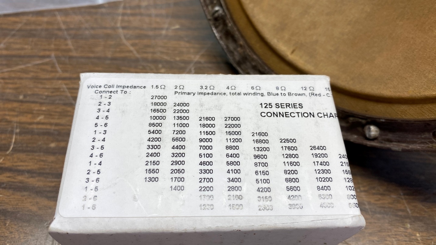
A handy connection chart was on the side of the new transformer box.
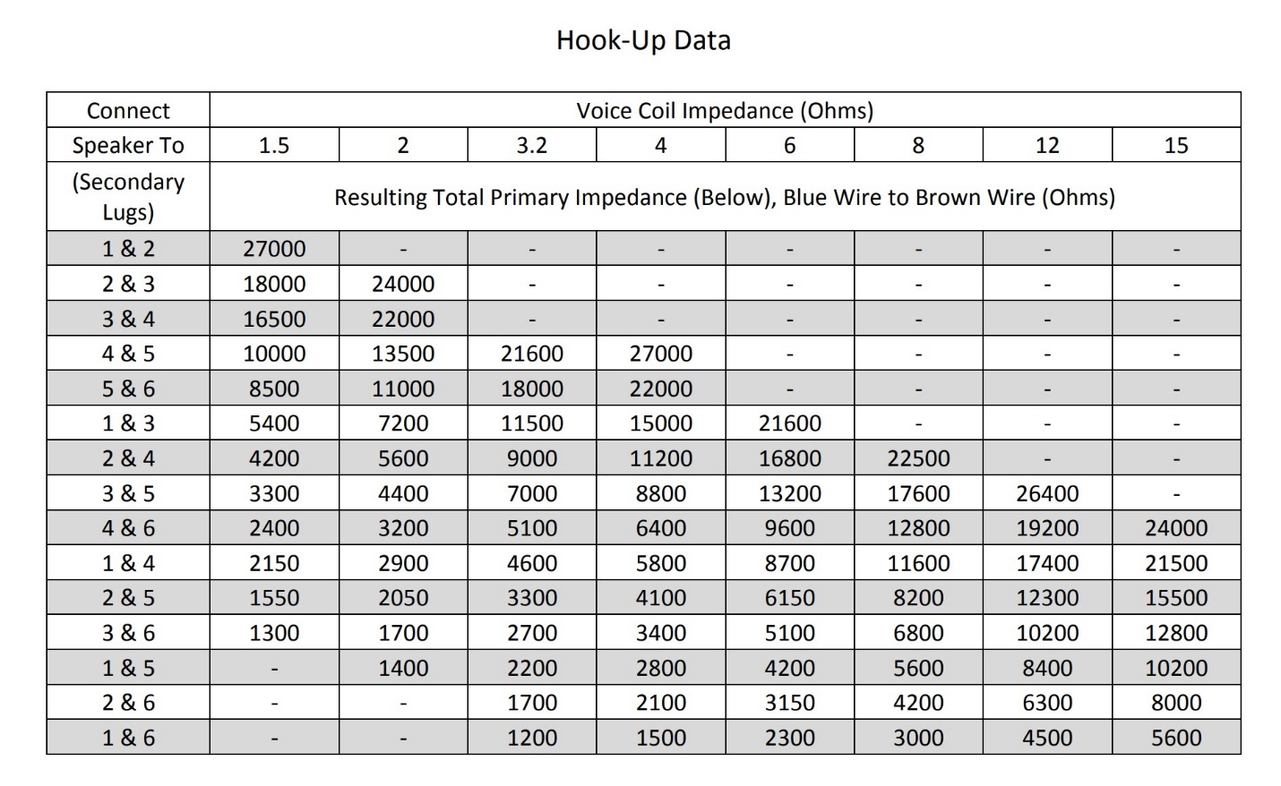
A better look at the same chart.
The lowest voice coil impedance given in the chart is 1.5 ohms, and the 6200 ohm primary impedance falls in between 5400 ohms (using output terminals 1 and 3) and 8500 ohms (using terminals 5 and 6).
So, I lugged the model 65 radio over to the workbench and connected this speaker to it, along with my longwire antenna.
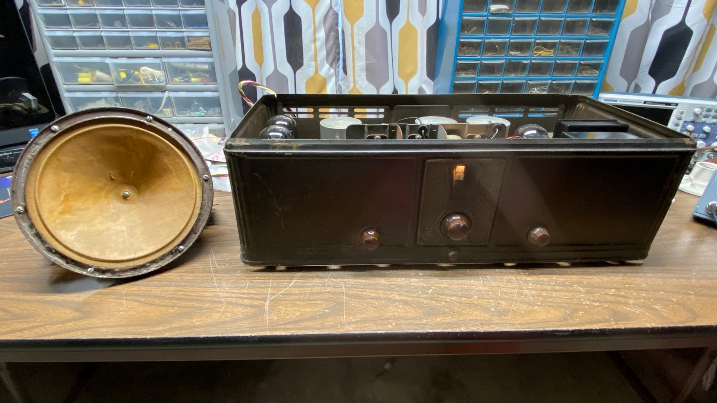
The rebuilt speaker is tested with the Philco model 65 radio.
I temporarily connected the new voice coil wires to terminals 1 and 3 of the new transformer and turned the radio on.
Soon, the radio was on and sounded louder than ever.
I switched the wires to terminals 5 and 6. I could not tell any difference in the sound.
Therefore, I put the wires back on terminals 1 and 3 and soldered them in place.
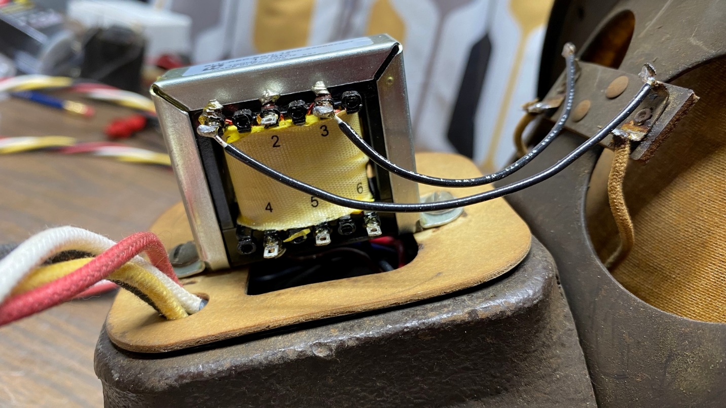
The new voice coil wires are now soldered to terminals 1 and 3 of the new transformer.
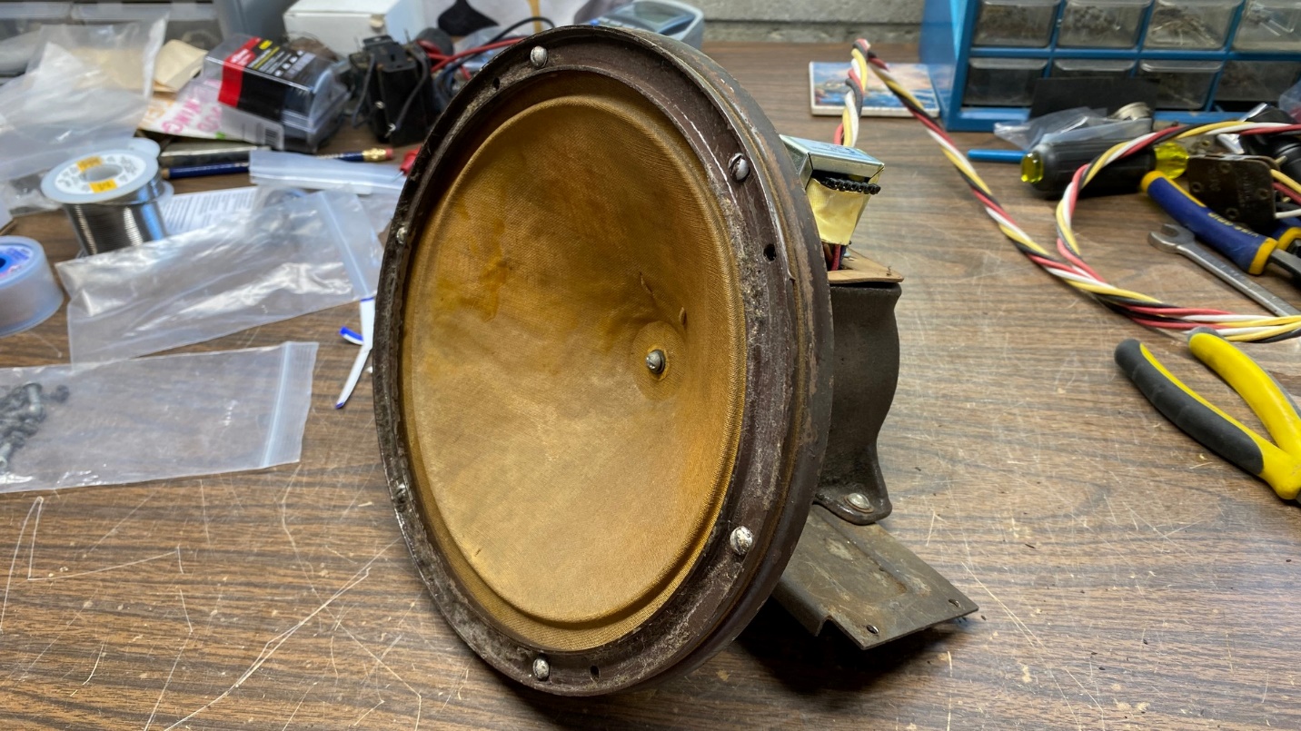
At this point the speaker looked like this:
The speaker is now ready to reinstall in its cabinet.
Electronically, the speaker is finished, and should be good to go for another 90 or so years. I still need to glue the gasket back to the trim ring, and it still needs to be reinstalled in one of the decorative cabinets I have. I wish to attempt to salvage the original grille cloth which is in the other F-10 cabinet I have and use it with this speaker. In order to do that, I shall have to acquire some Stitch Witchery. I have never used this product before, so this should be interesting. I will order it, and then discuss this as well as the final assembly of this speaker, in the upcoming fourth and final installment of this series.