I have had a Philco model 46 chassis and speaker sitting around here for many years; so many, in fact, that I have forgotten just how many years it has been.
Having divested myself of much of my Philco radio collection, I had decided that I would keep the various versions of the 1931-32 Philco cathedral models, which had been designed by Edward L. Combs. Those models are: 21, 46, 35, 70, 90, and the very early model 50 which was initially sold in the same cabinet as model 70.
Let me back up a bit. Model 21, 46, 35, 70, and the very early 50 are all essentially the same cabinet, modified as needed for the various chassis used in those cabinets. They are the same size. Model 90, on the other hand, looks much like its siblings but its Baby Grand cabinet is larger to accommodate the larger nine-tube chassis.
So anyway, I wanted to come up with a “home” for that long-homeless model 46 chassis and speaker.
In case you have never heard of model 46, it is, in essence, a version of Philco’s model 21. It was made to operate on 110 volts DC (direct current) only. Yes, in 1931, there were some parts of the country which still had DC lines even though, by then, alternating current or AC had practically become the de facto standard for electric service in the United States. If you wish to learn more about the “current wars,” or AC versus DC, you can find this information online from various sources.
Model 46 utilizes seven tubes along with a ballast tube. In the Baby Grand or cathedral cabinet, its outward appearance was identical to model 21.
Knowing a model 70 could be modified to accommodate a model 46, I decided to pursue this option.
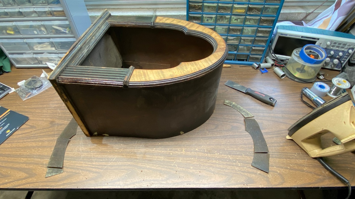
I had two model 70 cathedral cabinets, both in poor condition. One had had a great deal of wood filler placed onto the outside of the cabinet in a poor attempt to replace missing veneer, and looked terrible. This is the one which is shown in the picture above. The other cabinet had a crack on the side, but otherwise appeared to have potential as a restoration candidate. I decided to turn this cabinet into a model 46 Baby Grand cabinet.
I must apologize, but I forgot to take a “before” picture of this cabinet.
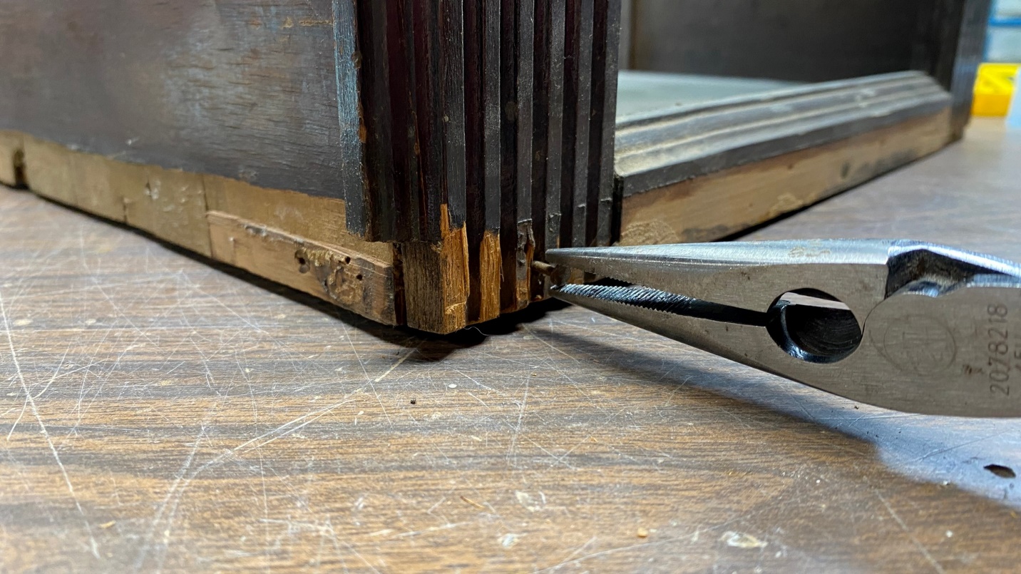
After removal of the bottom trim, I had to pull a few nails out as well.
I decided to begin by removing the bottom trim of the cabinet, which was in poor condition with missing and broken spots. The trim came off easily, but left some of the mounting nails behind, these were pulled with my large, heavy duty needle nose pliers as shown above.
A piece of the cabinet, which is attached below the front panel, has come loose as shown above.
I noticed that a piece of the cabinet, which attaches to the cabinet body at the bottom front, had come loose. I would have to wait and deal with that later.
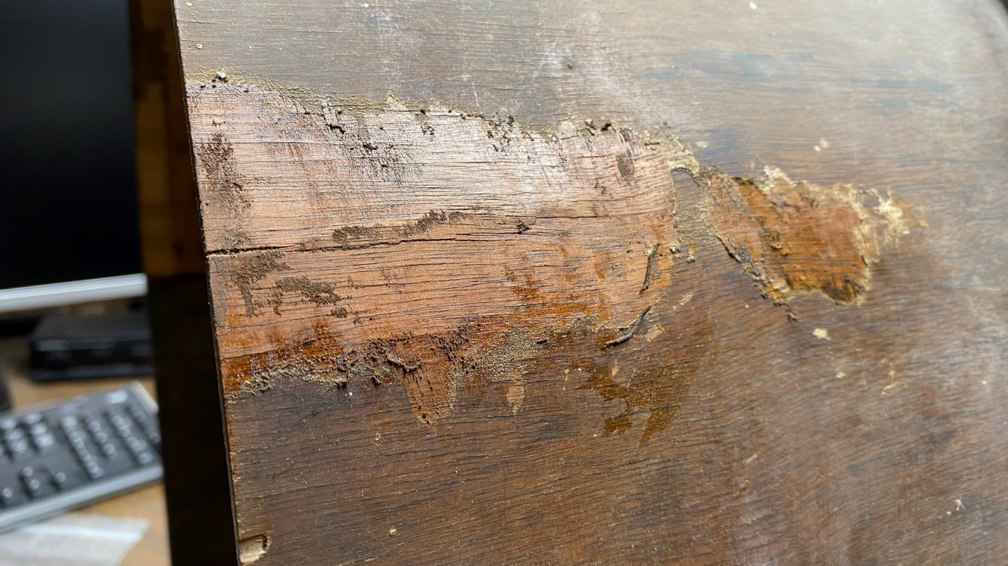
Before I went any further with this cabinet, I wanted to see if I could repair that crack in the upper right side of the cabinet.
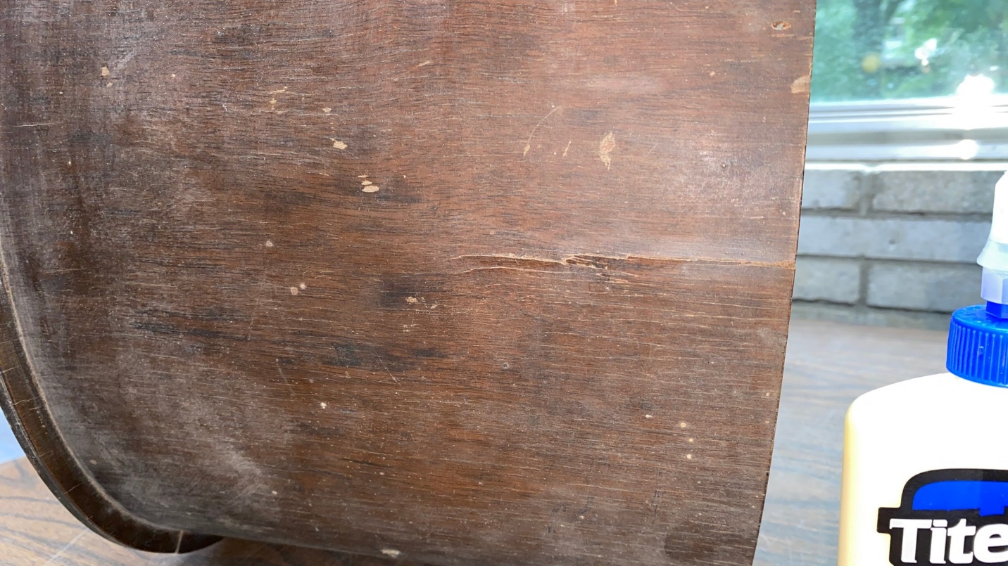
A crack in the cabinet may be seen.
A close inspection revealed that the outer veneer had the crack, but the inner substrate seemed to be fine. So, I did my best to get some Titebond II wood glue under this crack . Then, using an old steam iron I had purchased several years ago at a yard sale for 50 cents just for this purpose, I ironed the crack until the glue had set.
The crack has now been glued.
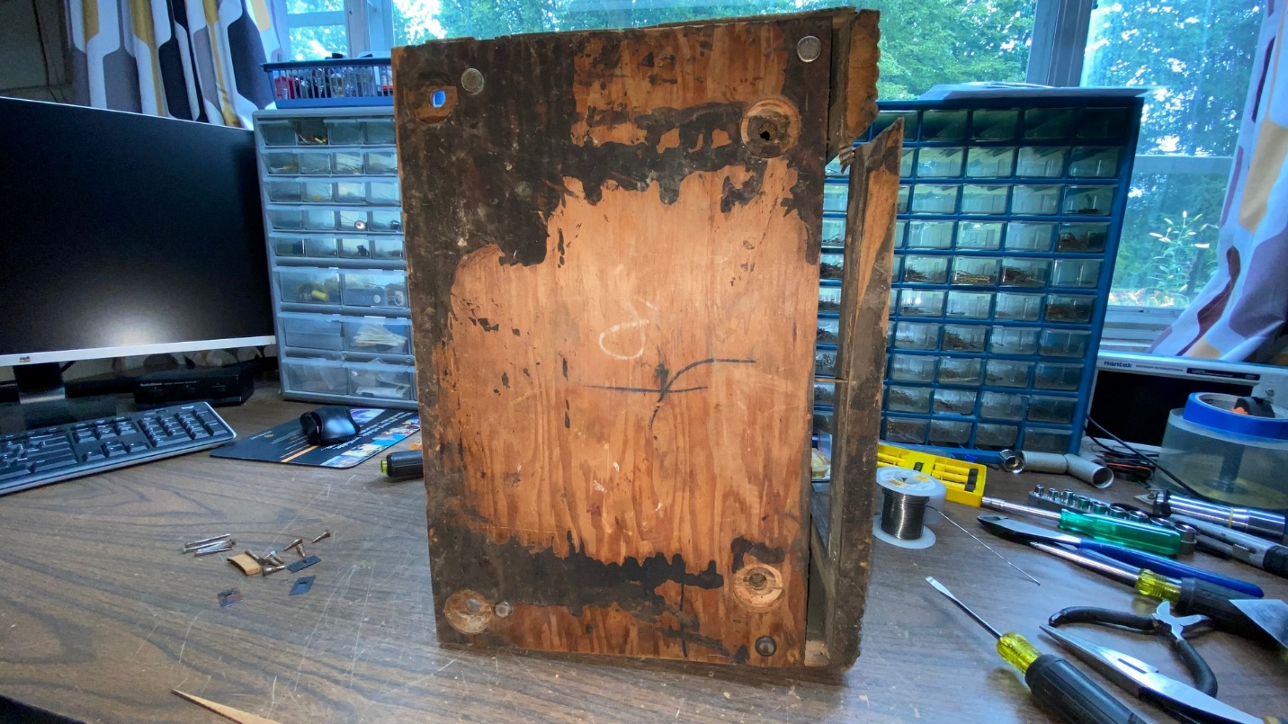
I had to remove the cabinet’s bottom and replace it with a different one, as the 70 cabinet base was drilled with four holes to accommodate the 70 chassis. Model 46, as well as model 21, has but three mounting holes.
Steve Davis furnished a new cabinet bottom, a rear arch (which was missing), and a new front panel drilled for a model 21 or 46 chassis (three control shafts instead of four as used in model 70).
Knowing that repaired crack needed the stability of a rear arch to help ensure it would not reopen, I then glued the new rear arch to the back of the cabinet.
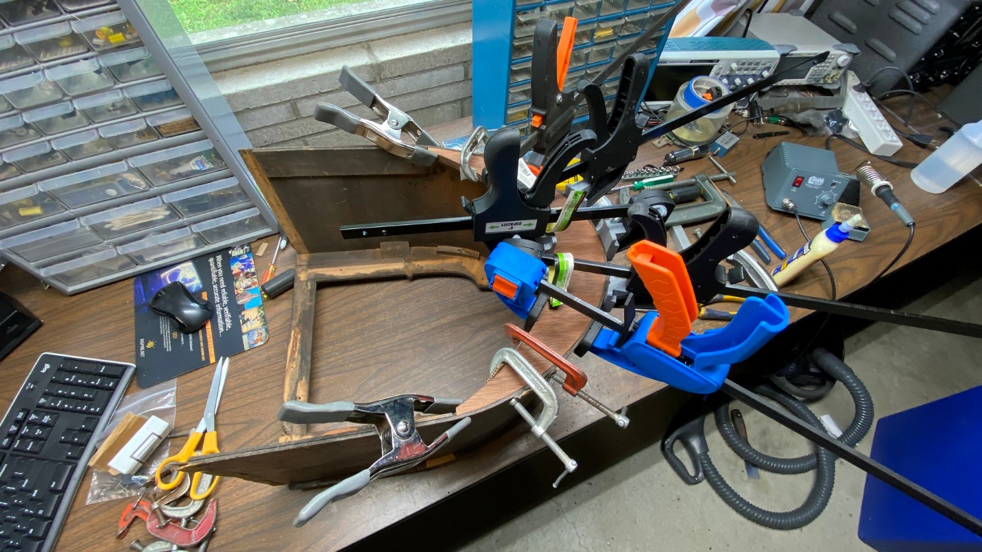
Gluing the new rear arch to the cabinet.
I had already removed the old model 70 (four hole) base, as you may see in the photo above.
Once the glue was dry, the multiple clamps were removed and the new rear arch was secure and stable.
My next job was to reglue the cabinet in areas where it had become delaminated, notably on the back edges.
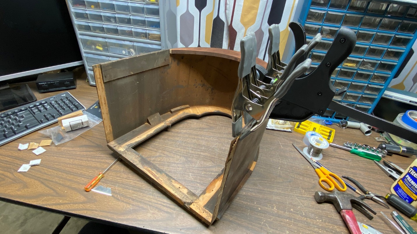
Gluing one back edge of the cabinet where it had become delaminated.
I glued one edge at a time, using several spring clips to hold the plies together as the glue dried. The process was then repeated for the other back edge.
Now, it was time to install the new cabinet base. I first hammered in four new reproduction cabinet feet, and then I glued the new base into position on the bottom of the cabinet. Before doing so, however, I made very sure the bolt holes were oriented properly!
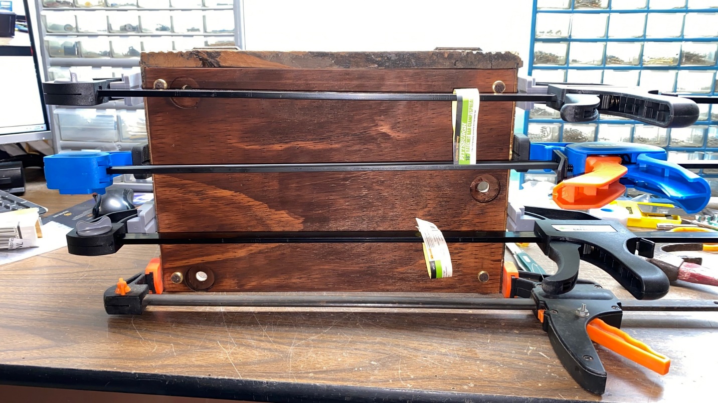
Gluing the new base to the cabinet.
Originally, the base had been held in position on the cabinet with a combination of glue and nails. I decided to just use glue on the sides of the cabinet. On the cabinet front, I reinstalled the loose piece which was originally installed at the bottom of the cabinet front. I did nail this piece in place as it had been originally, using the original nails which had come out unbent, amazingly!
Well, I have done a lot of work to this cabinet thus far, but there is a lot more work to do. In the next installment, I will begin to replace several pieces of missing veneer. Please join me then.