I had been thinking about the Philco model 38-14T which I had refurbished ten years ago. As you may recall from that post, I not only brought it back to proper operation, I also “modernized” it to 1940s standards with the use of tubes which did not require a dropping resistor in the filament circuit. This had been done in the 38-14 mostly out of necessity, as it was missing its dropping resistor.
I had been wondering for a couple months if I could do the same thing to a Philco model 54C. If you are not familiar with model 54, let’s go over its schematic.
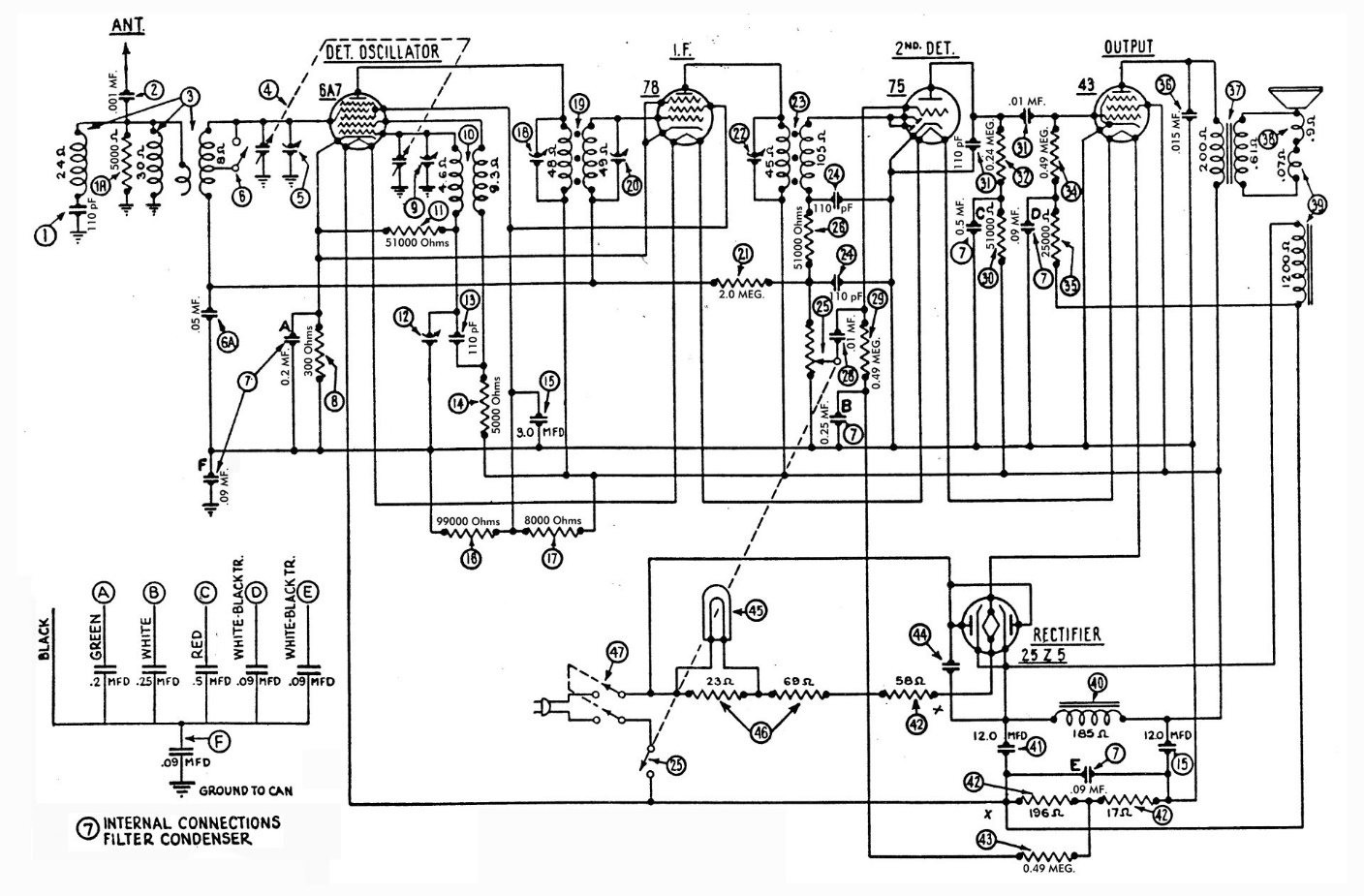
Original Philco model 54 schematic. Click here to see a larger version.
If you are not familiar with model 54, you should be aware that it uses two very large power resistors mounted on top of the chassis to drop the filament voltage from the 115 volt line to the total of 68.9 volts needed by the filaments of the tubes originally used in this radio.
To further explain my thoughts regarding this radio, allow me to take some time to discuss the All-American Five radio circuit.
In the early 1930s, during the worst times of the Great Depression, radio manufacturers were trying to find ways to make radios cheaper so they would be able to sell radios to people who could really not afford to buy one. One of the circuits developed during this time became known as the All-American Five circuit simply because it used five tubes in a circuit which could operate on AC or DC current and required no power transformer.
A major drawback of this circuit was because the tubes which were available at the time required a dropping resistor to operate with their filaments connected in series. In the Philco model 54, resistors (42) and (46) dropped the incoming line voltage to a level which would allow the tube filaments to operate safely.
As bad as those large power resistors were, some manufacturers devised other, less safe schemes such as the resistor power cord, which incorporated a long resistor into the set’s power cord. The cords ran warm to hot in operation and became known as “curtain burners” as some were known to catch curtains on fire if the cord was left bunched up rather than spread out as they were designed to be. You can read more about these here.
Anyway, tubes were eventually developed with higher filament voltages, designed for use in the All-American Five circuit, which eliminated the need for dropping resistors and resistance line cords. Octal-based tubes designed for this purpose included the 12A8GT and 12SA7 converter; the 12SK7 IF amplifier; the 12SQ7 detector and first audio amplifier; 50L6GT audio output; and 35Z5GT rectifier. If you will recall from my Philco 38-14T post, I converted that radio to use these tubes which eliminated the need for filament dropping resistors.
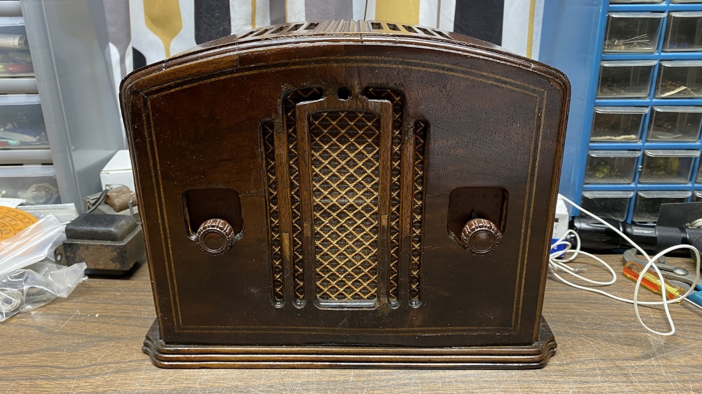
I wanted to do the same thing with a Philco model 54C. I therefore set out to find a somewhat rough 54C to make this conversion. It did not take long after posting a “Wanted” ad on the Philco Phorum and Antique Radio Forum (ARF) – someone on ARF soon offered to sell me a 54C at a very reasonable price.
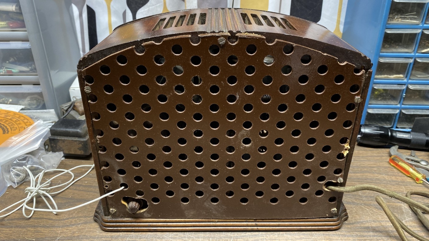
Back view of the 54C I purchased from an ARF member. The front view may be seen at the top of this page.
When the 54C arrived at my home, I looked it over carefully. As you will notice from the photo at the top of this post, the cabinet is missing some veneer on the front. And as you may see above, the original metal back is missing. In its place was a crude homemade back as may be seen just above.
I removed the back and took a closer look.
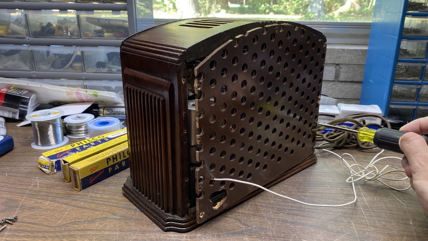
Removing the back of the radio.
Once the back was removed, I was able to get a peek at the chassis.
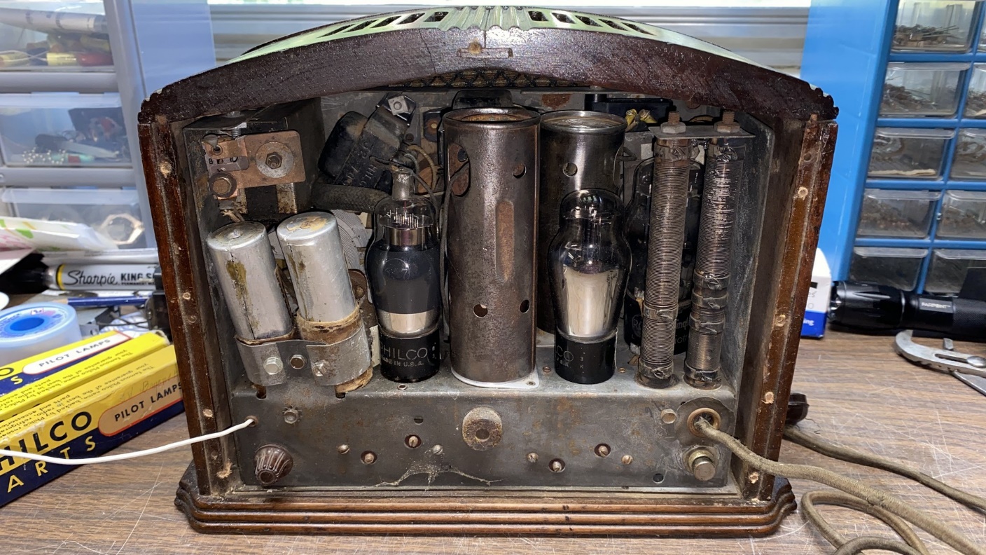
Rear view of the 54C with the back removed.
Let’s take a closer look at those electrolytic capacitor cans.
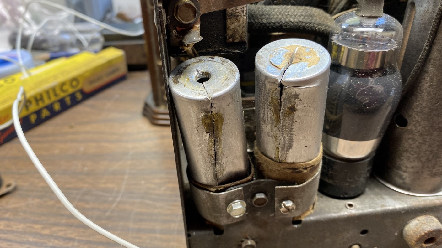
A closer look at the electrolytic capacitor cans.
Wow! Someone opened those cans up the hard way – by cutting them vertically instead of horizontally near the bottom of each can, as I would have done.
So far, the chassis looked perfect for the conversion project which I had in mind.
This will be a very long and involved project, and the story will need to be told over multiple posts. So, let’s temporarily pause here. Next time, I will share the changes I have in mind for this radio, and I will get started taking the set apart so that the conversion can be made.