When we last discussed this project last year – three weeks ago – I had mostly reassembled the oscillator section and had reattached it to the sub-base. After taking a Christmas/New Year’s break from this project, I returned to it last week and began by adding the final components to the oscillator section.
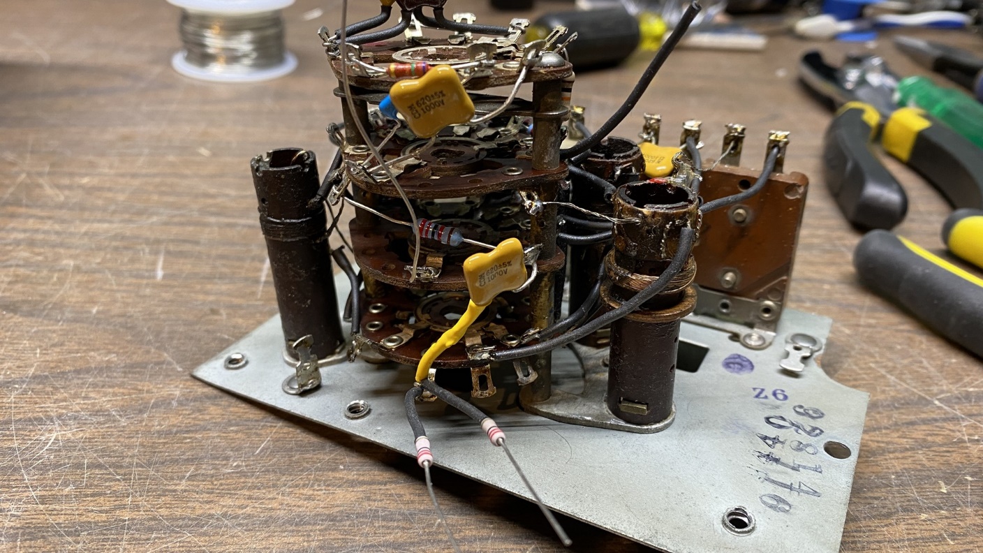
Almost completely rebuilt, the 37-116 oscillator section will soon be ready for reinstallation.
I removed the oscillator section from the sub-base in order to finish installing some of the new components. It is a good thing I did so. I discovered that I had made some errors in wiring. Instead of connecting resistors (34) and (35) to switch terminals J10 and J9, respectively, I had connected them to terminals J9 and J8. Oops. I quickly corrected that error before going any further.
See the switch hookup below.
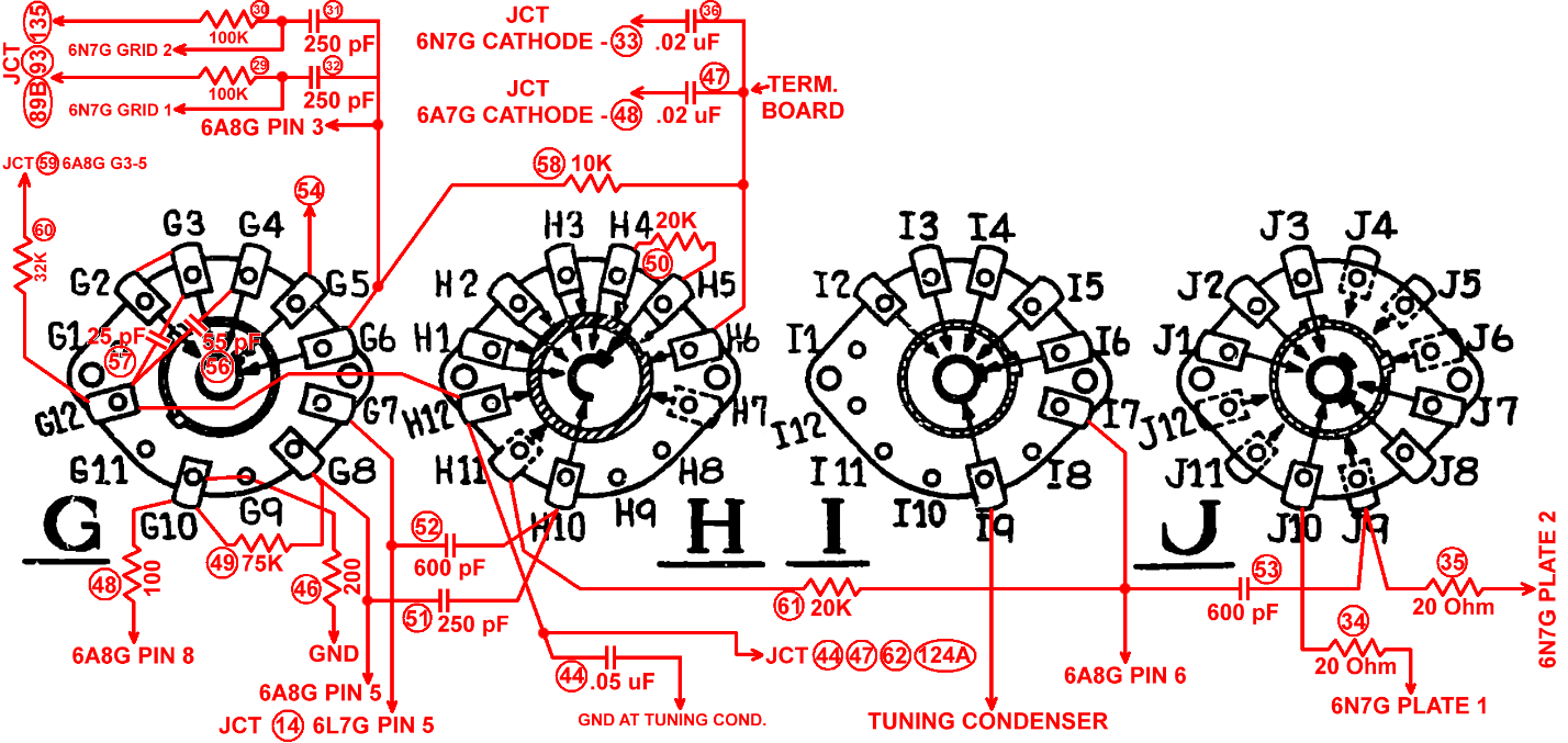
37-116 oscillator section switch wiring
Everything else looked okay, and therefore I proceeded to connect the remaining components and to reattach the oscillator section to the sub-base.
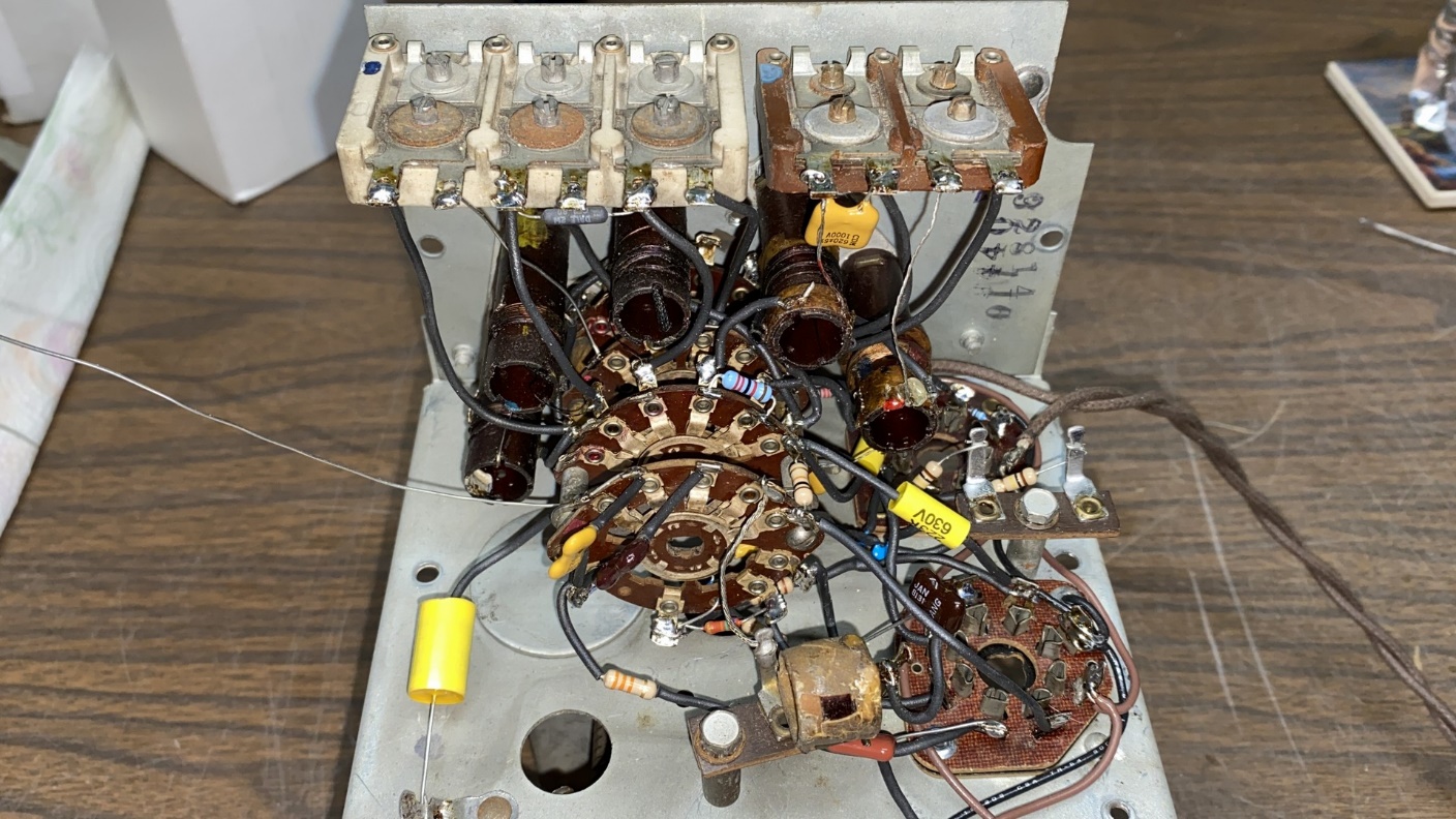
Oscillator section reinstalled on sub-base
Feeling more confident at this point, I went ahead and reattached the converter (RF) and the antenna sections to the sub-base and reinstalled the switch shaft.
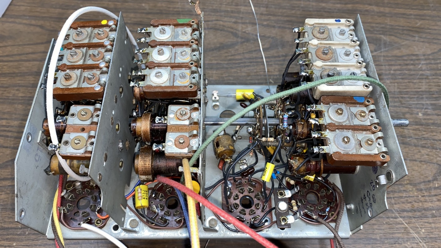
All sections reassembled on the sub-base
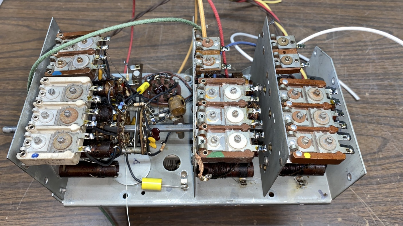
Another view of the rebuilt RF unit
Having reinstalled the switch shaft and attaching its two bolts, something told me I should try switching the assembly through its five positions.
Immediately something did not feel – or sound – right.
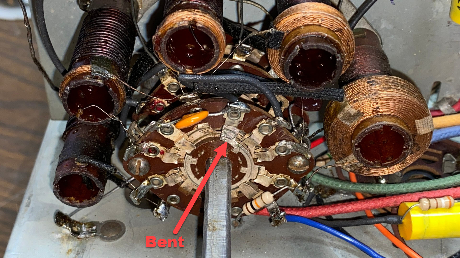
I looked…and saw a bent switch contact on the rotor of section D, which is part of the converter or RF section.
Just what I needed…another problem.
Beautiful.
And of course, switch section D – the last section on the assembly when you disassemble the three section stack – is the one with the bent contact. This would necessitate a total re-disassembly of the RF section, replacement of the bad switch wafer, and re-reassembly.
And then I remembered something…
Next time, I will tell you about what I remembered and what I decided to do to get myself out of this mess.