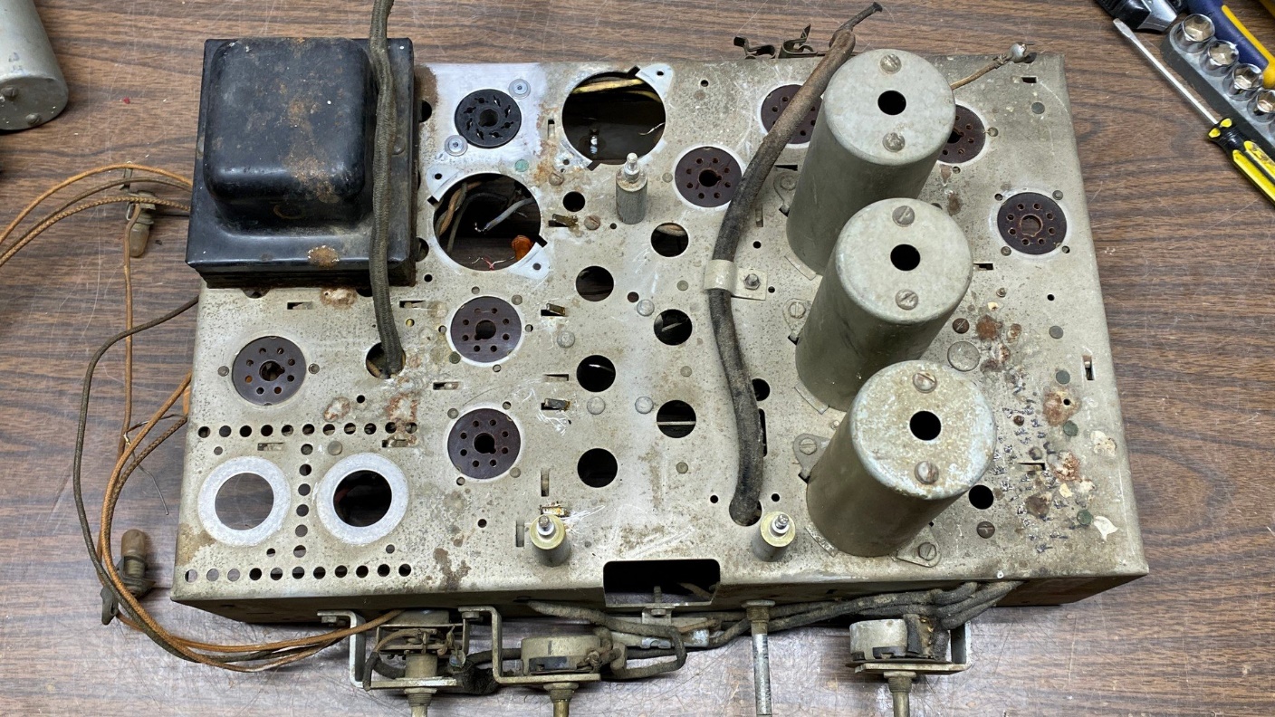
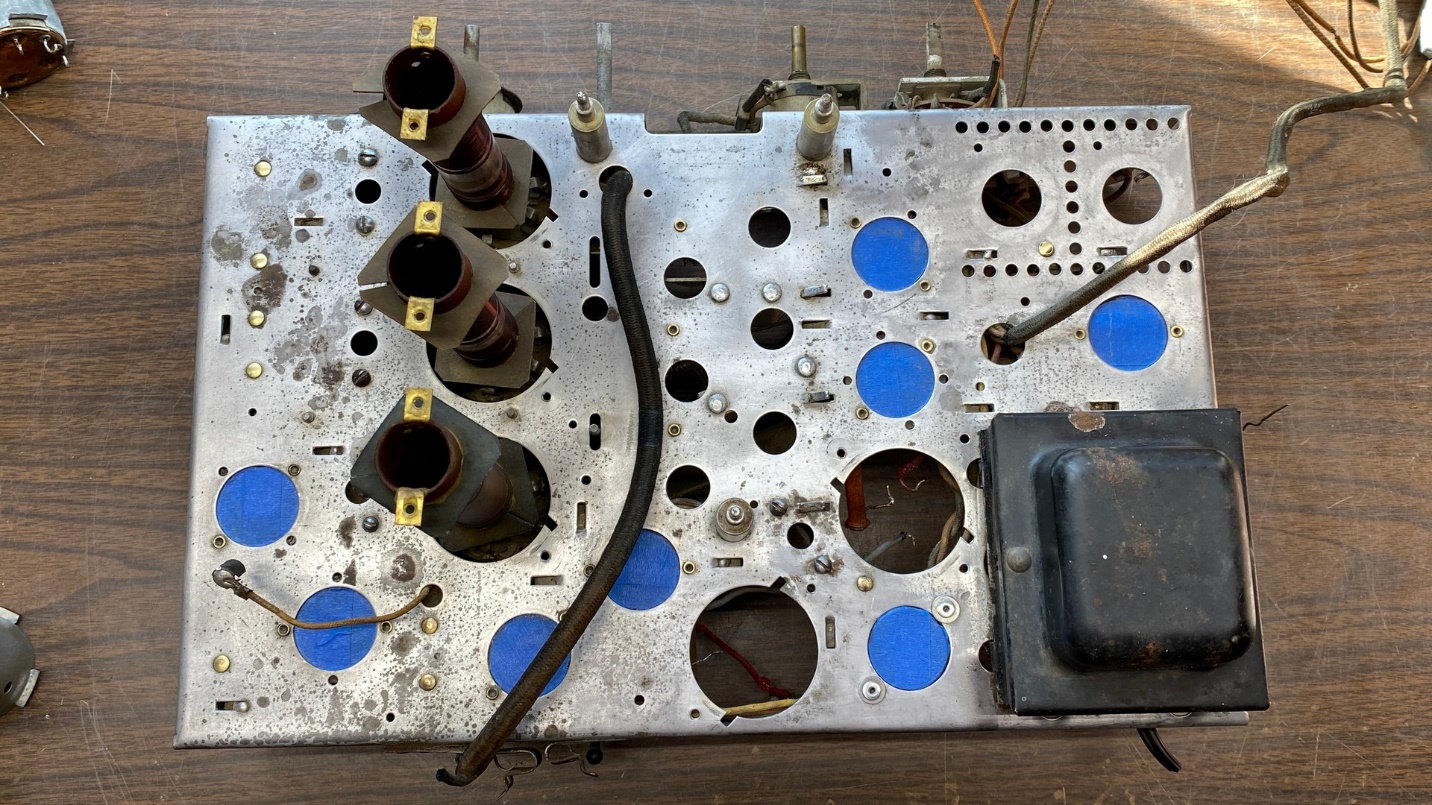
As you may recall in the last installment of this series, I was considering my options for cleaning the top of the T9-10 chassis.
In the photo above, it doesn’t look too dirty. But in reality, the top of the chassis was extremely grungy, dirty, nasty, filthy…pick the word you like, it is applicable.
I knew that if I cleaned the top of the chassis, the note written by the previous “repairman” would be lost. I decided it was worth losing the handwritten note, as it was more important to me to get that filth off the chassis to the best of my ability.
While I pondered my options, the T8-14 parts chassis I had ordered arrived via FedEx.
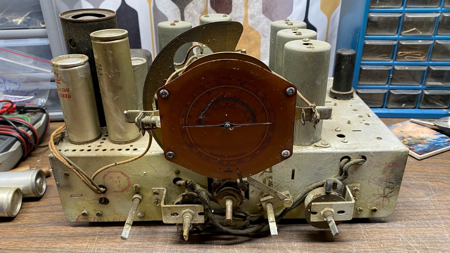
An RCA T8-14 parts chassis. This is very similar to the T9-10 chassis.
The main difference between the two chassis, besides the absence of a 6E5 tuning eye in the T8-14, was that the T8-14 uses a 5Z3 rectifier with a metal shield, while the T9-10 uses a metal octal based 5Z4 tube.
The first thing I checked was the T8-14’s tuning condenser – which was the reason I bought the chassis in the first place.
Fortunately, it was good and had no obvious damage at all.
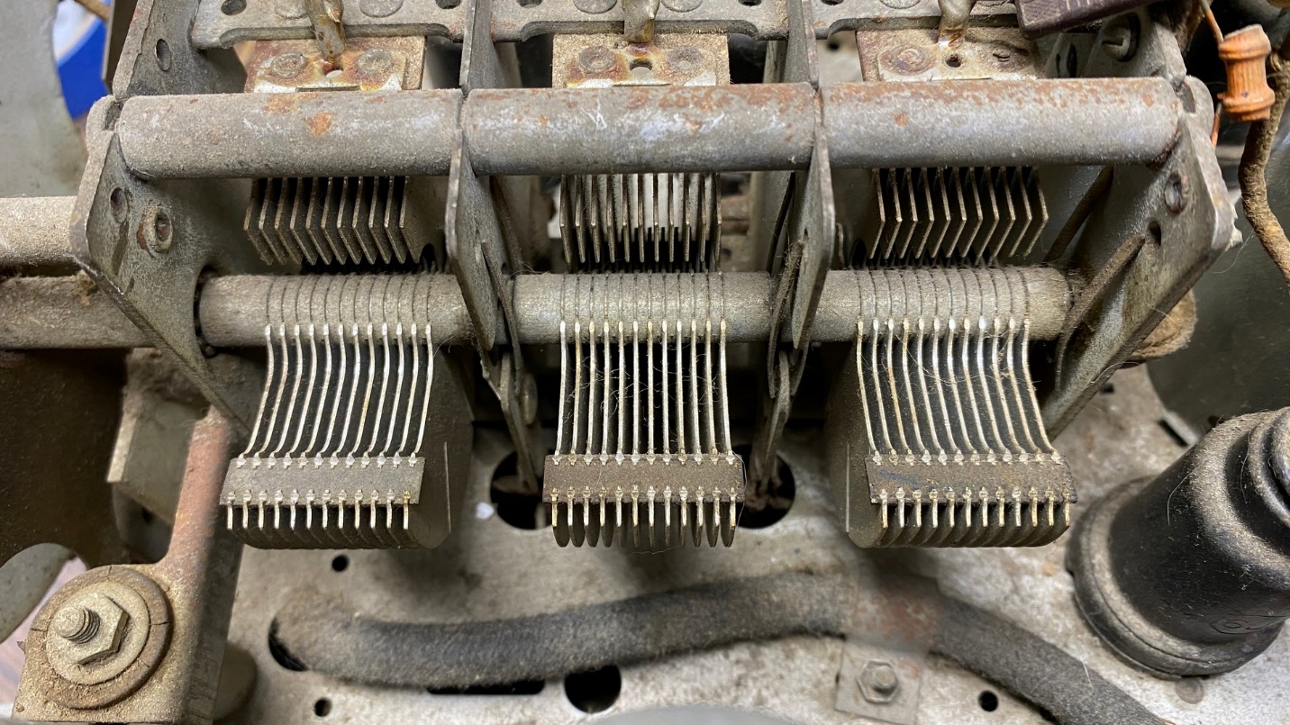
The T8-14’s tuning condenser is in good shape.
I then set the parts chassis aside. I had decided to clean the T9-10’s chassis first, and then replace all needed rubber-covered wiring, resistors, and also restuff the paper and electrolytic capacitors before I installed the replacement tuning condenser on the chassis.
I had purchased a two-pack of Dremel abrasive buff wheels. However, I found that in using them, they were great at removing dirt and grime but they did not last very long at all.
The photo below shows how far I managed to get using both buffing wheels, before both self-destructed.
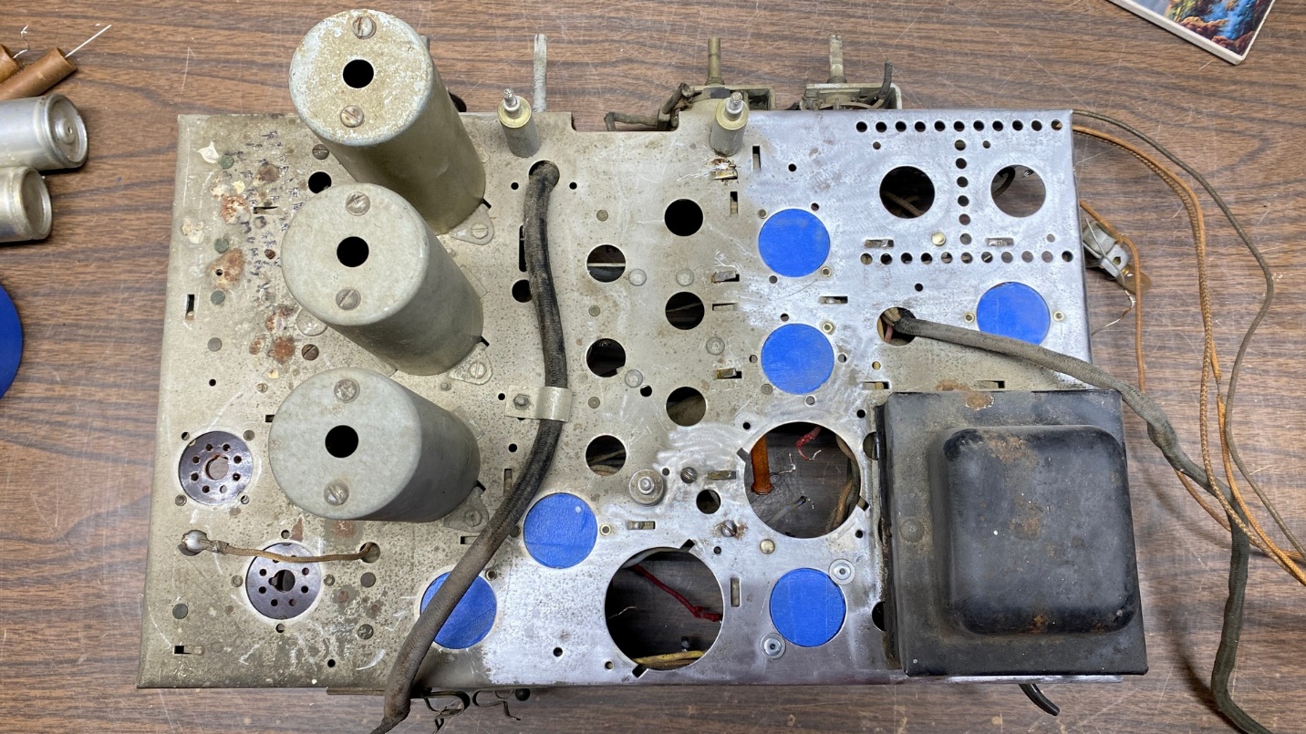
A partially cleaned T9-10 radio chassis.
By now, I realized that I should have simply used hand cleaner with pumice.
I had a can on hand. Or, at least I thought I did.
When I opened the can, I found it was all but empty.
I wondered to myself, Why did I save this can?
There was nothing else to do but purchase another can of orange hand cleaner with pumice.
Once I had the new can of cleaner, I taped over the two remaining tube sockets and carefully removed the cylindrical shields from the three RF coils. I also removed the clamp holding the shielded antenna cable in place on top of the chassis.
I then proceeded to carefully scrub the rest of the top of the chassis using the hand cleaner. It did an excellent job of getting rid of the dirt and grime.
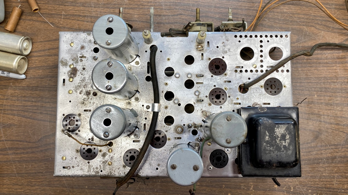
When I was finished, the chassis looked as shown below.
How the chassis looked after a thorough cleaning.
Next, I began to clean and polish each of the aluminum coil shields. (I had previously cleaned and polished the IF transformer shields, and remounted the IF transformers inside each shield.)
I discovered that these shields do not polish to a mirror-like finish as do most Philco IF shields but remain mostly dull. They do respond very well to a rubdown with steel wool prior to polishing with Mothers Mag & Aluminum Polish.
These coil shields have flanges on the bottom ends. Each shield is held in place with two pieces of metal used as clamps on two of the four flanges.
I found that one of the coil shields had cracks at its flanges. Fortunately, the T8-14 parts chassis had all its coil shields. I therefore pulled a coil shield from the T8-14 chassis which had undamaged flanges, and gave it a good cleaning and polishing.
Once I was finished, all three shields were reinstalled over the coils on top of the chassis, and I reinstalled the clamp which holds the shielded antenna cable in place. I also bolted the IF transformers back into place – but did not rewire them into the radio circuitry yet.
All coil shields and IF transformers remounted on top of the now-clean chassis.
Now comes the restuffing of capacitors and replacement of resistors and rubber-covered wire. I prefer to use 20 gauge PVC insulated hookup wire rated at 600 volts to replace the old rubber-covered wires. I was nearly out of 600 volt rated wire, and needed more to work on this set. I soon discovered, much to my dismay, that it was easy to find 300 volt rated wire but not 600 volt wire!
Next time, I will tell you how I finally managed to find some wire, and I will also proceed with the recapping, rewiring, and re-resistoring. Stay tuned!