Various and sundry issues are (mostly) taken care of.
Today, I am going to attempt to take care of several small issues in the model 87 chassis.
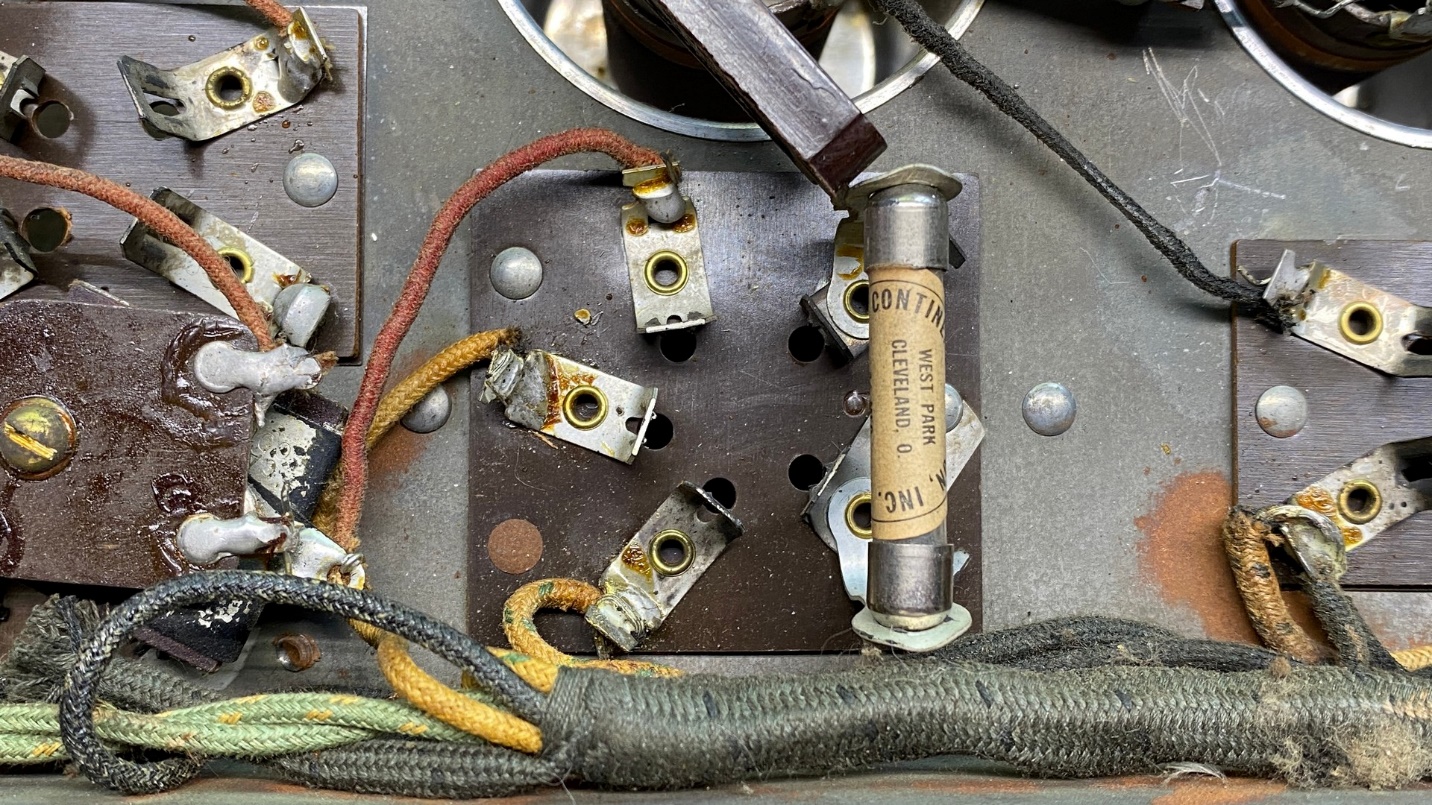
The grid leak, part (20).
I removed the set’s grid leak resistor, part (20), from its clips under the chassis. Noticing the label stated a value of 0.75 megohms, I measured it and found it had not increased a lot – it measured 1 megohm.
I put it back for now. After the radio is back in operation, I may change it for a 2 megohm resistor. In my prior experimentation with 1920s radios using a grid leak in the detector circuit, I found that a 2 megohm resistor seemed to give the best and most consistent results as a grid leak in various radios, including the early Philcos.
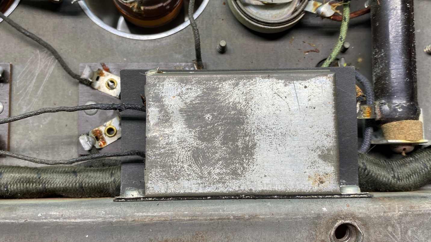
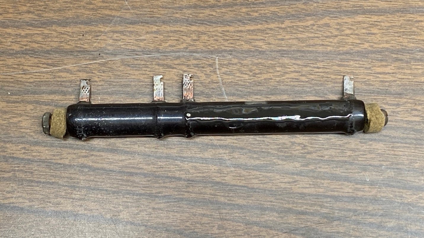
Next, I turned my attention to the dual filament bypass capacitor, part (27).
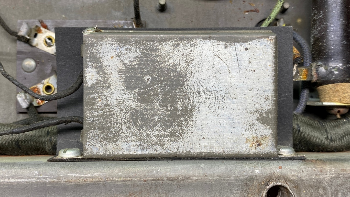
The filament bypass capacitor, part (27).
If you have restored Philco radios such as models 90 and 112, this rectangular can should look familiar, for it is the same type of capacitor. This particular can holds two 0.5 uF paper capacitors, sealed with a black waxy substance.
This can is easy to rebuild, and I will now show you how it is done.
First, remove the two screws holding the can to the chassis, Set the screws and the black fiber insulator aside for now. Do not remove the wires from where they are attached.
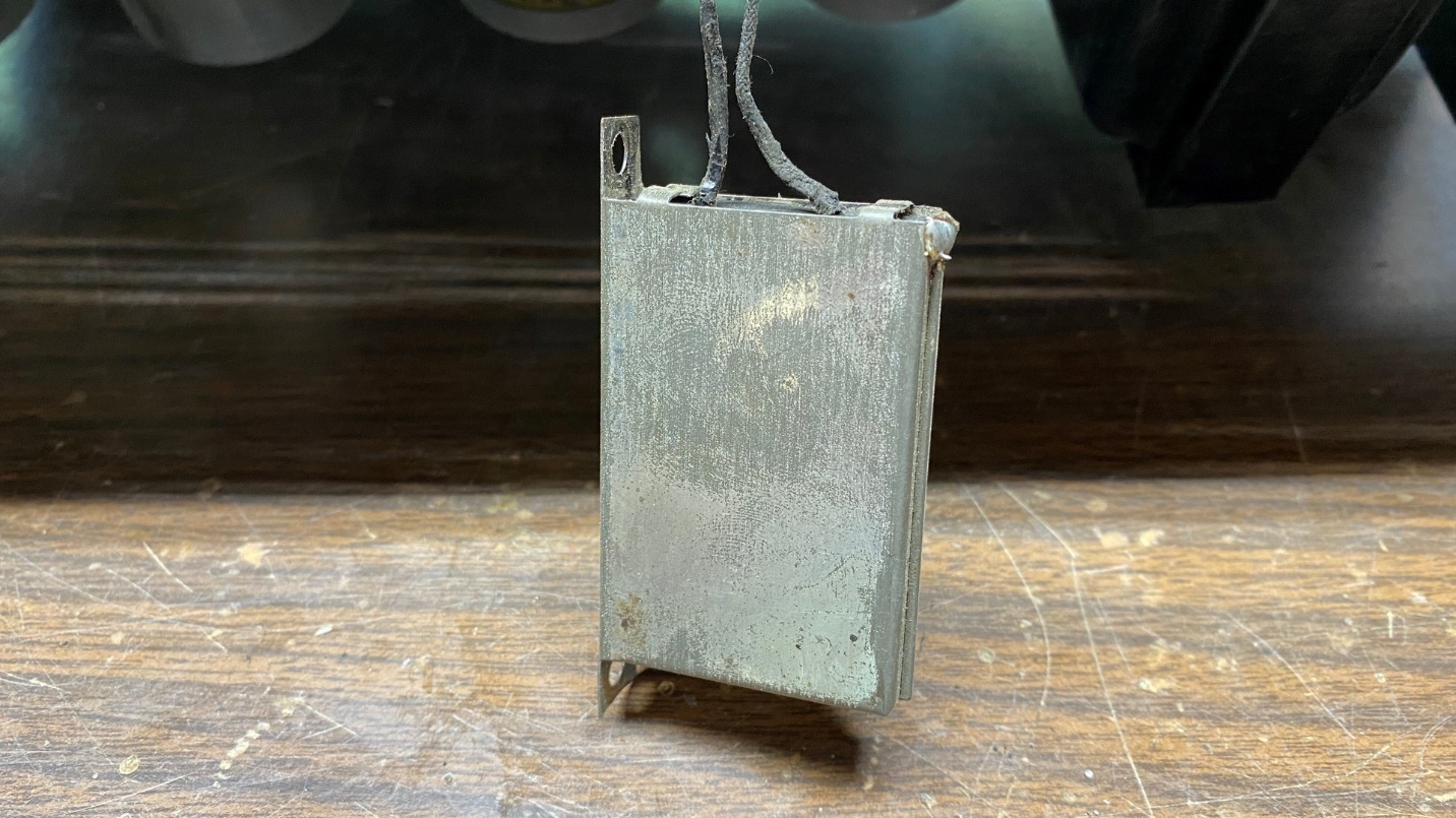
The two-capacitor assembly is removed from the chassis, but the wires are not disconnected.
Notice there are four small tabs on the end of the can where the wires come out. Unfold these tabs, and then pull the insides straight out.
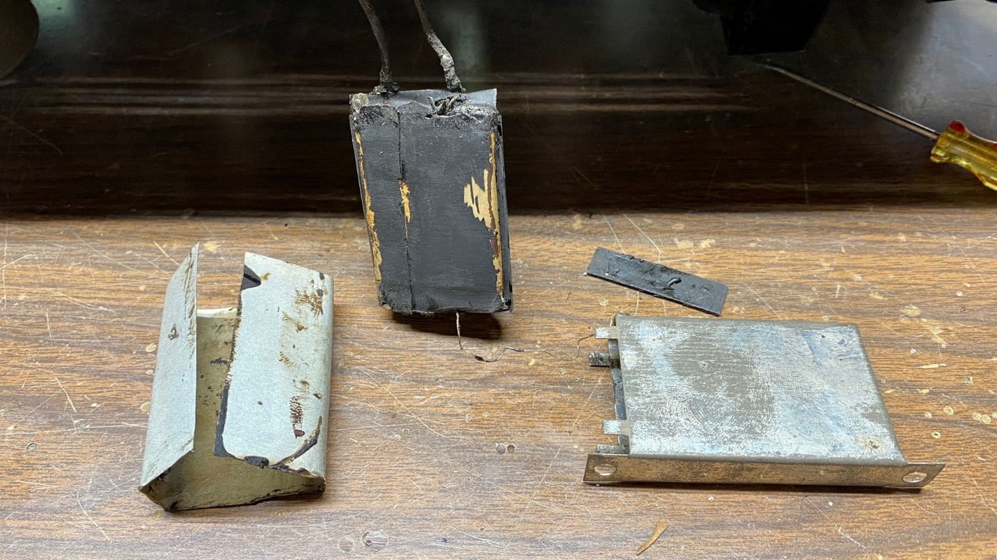
The assembly is disassembled in preparation for rebuilding.
Unwrap the paper from the capacitor assembly. A small rectangular fiber insulator usually comes out with the capacitor assembly. Place the insulator back into the can – it lays flat against the far end of the can – and then put the gray paper insulation back into the can.
Pull the wires from each end of the capacitor assembly. Do not remove the fiber insulator through which the wires protrude. Small metal contacts will remain on the wires as they are soldered in place. Using your soldering iron or soldering gun, remove these metal tabs.
Now you should have three wires – one bare, two with black insulation.
Get two 0.47 uF, 630V capacitors, the smallest ones you can find. The small red caps shown in the photo below will suffice.
Place the two new capacitors together, side by side. On one end, twist the leads together. Also attach the bare wire to these twisted leads. Solder them together. This will be the grounded end – notice how the skinny bare wire is also soldered to the can.
Now, on the other end of the new capacitors, solder one black wire to one lead of a new capacitor. Solder the other black wire to the remaining lead of the other capacitor.
When finished, it should look as shown in the photo below.
Two new 0.47 uF, 630V capacitors are used to replace the original 0.5 uF caps.
Notice how I used two small pieces of heat shrink tubing over the soldered ends of the capacitors where the black wires are connected.
Now, push the new capacitors into the can. If needed, you can add a little hot glue to further insulate the wires where they were soldered. Put the fiber insulator, through which the wires protrude, back into place on the end of the can and fold the four tabs over.
Voila, we have rebuilt this can and it retains its original appearance.
The old capacitor can (27) with new parts inside.
There is a 1 watt resistor connected to the terminal board of the big filter capacitor can assembly. It is part (34) and is 70K ohms. See the photo below.
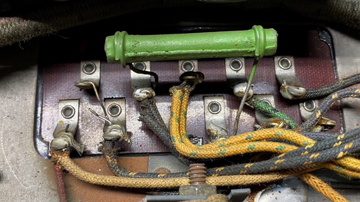
A 70K resistor, part (34), needs to be replaced.
I will replace this resistor, but I will have to order one – I do not have any 1 watt 68K resistors on hand. Yes, I will have to replace with a 68K resistor since 70K is no longer a standard value. 68K is well within 5% tolerance of 70K – and back in 1929, resistors were seldom held to a tighter tolerance than 20%.
New I will move on to part (35), the large ceramic three-section resistor.
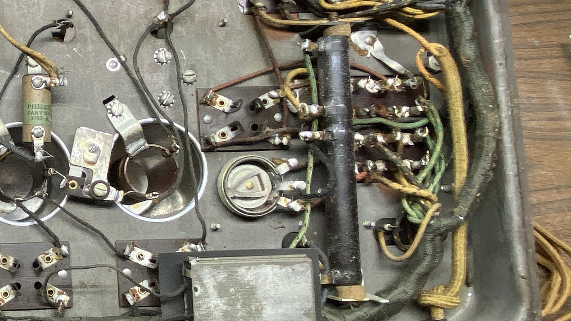
The large three-section resistor, part (35), just right of center.
As you may recall, this resistor includes a 3785 ohm, a 157 ohm and a 640 ohm resistor on one ceramic tube. Recall also that the 3785 ohm section is open.
I needed to ensure that I could safely connect a new resistor (or resistors) across the terminals of the 3785 ohm section without being concerned that the old section might suddenly, intermittently or otherwise, become “live” again and interfere with the proper function of the radio.
I asked about this issue on the Philco Phorum. I received a few answers, but none were really to my liking.
And then I thought of an email I had received a few days ago from a friend on this subject.
Here is how I chose to handle the situation.
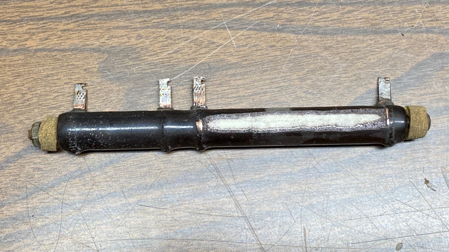
The 3785 ohm section has been effectively removed.
Using my handy-dandy Ryobi “Dremel” tool, I ground off the resistor’s outer coating, and ground off enough of the resistance wire underneath the coating that this section is now, without question, permanently “open”. Now I can connect a resistor, or resistors, across these terminals safely in order to replace the original 3785 ohm section of this resistor.
(Thanks to my friend Ed L. for the idea.)
Later, I coated the ground-off area with J-B Kwik (a fast drying version of J-B Weld) to insulate the spot and ensure that no shorts will occur. Once the J-B Kwik dried, I rechecked resistances between the terminals. Nothing had changed – the 640 ohm section read 639 ohms; the 157 ohm section read 160 ohms; and there was infinite resistance between the terminals which formerly comprised the 3785 ohm section.
The three-section resistor, now coated with J-B Kwik where it had been ground off, is ready for reinstallation in the 87 chassis.
Next, I needed to figure out the wattage needed for this resistor. We know the resistances – 3785 ohms, 157 ohms, and 640 ohms. The 157 ohm section was measured at 160 ohms, close enough. The 640 ohm section measured right at 640 ohms.
So how do we figure out the wattages of these resistors?
(I am going to give you the wattages of all three sections for reference, even though I only need to replace the 3785 ohm section of this resistor.)
Rider’s Manual Volume II gives part of the information found in the Philco model 87 service manual. This Philco manual tells you everything you need to know about the 87 except the values of the resistors and capacitors. You see, back in the 1920s, parts values, and even schematics, were considered proprietary information. Thanks to the efforts of people such as John F. Rider, the publisher of Rider’s Manuals, manufacturers began to realize that if they expected their radios to be repaired and maintained, that the radio repairman (or Service Man as they were called back then) needed complete, comprehensive information on radios in order to intelligently service them.
So anyway, on Philco page 2-20 of Rider’s volume II, some charts are given. Among those is Table 5, giving the voltages across this three-section resistor. Just what we need!
The 3785 ohm section has a 90 volt drop.
The 157 ohm section has a 6 volt drop.
The 640 ohm section has a 45 volt drop.
With this information, we can use this formula for calculating wattage:
P = E2 R
Which means, Power (Wattage) equals E (Voltage) squared times R (Resistance).
Or you can cheat and use the online calculator found here.
Here are the results:
The 3785 ohm section calculates out to 2.14 watts.
The 157 ohm section calculates out to 0.23 watts.
The 640 ohm section calculates out to 3.164 watts.
It is recommended that any calculated wattage be doubled in practice for safety.
Therefore –
3785 ohms, 5 watts
157 ohms, ½ watt (I would use 1 watt)
640 ohms, 7 watts
The next problem is the fact that 3785 ohms is not a standard value for any 5 watt resistor stocked by Mouser Electronics, one of my favorite parts suppliers. The closest value is 3900 ohms, and that is what I am going to go with. So now I will need to order this, as well as a 70K, 1 watt resistor.
While I wait for those parts to come in, there is an issue with the set’s power transformer which I need to take care of. I will explain what and why in the next installment of this Philco model 87 repair series.