The Philco model 604 is a five tube AC/DC table model radio. It was introduced at mid-season (January 1936). It is unusual in that it has the dial and controls on top, with a Bakelite control panel mounted on a cabinet made of Walnut veneer. Unlike the RCA Victor Q10 [that I previously worked on], Philco completely isolated the chassis of the 604 from the AC line.
I purchased this set at a swap meet in Ohio several years ago. I first set this Philco on my workbench in early June 2015.
Some chassis shots:
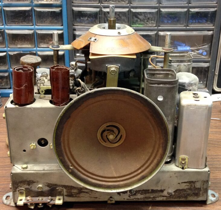
Front View
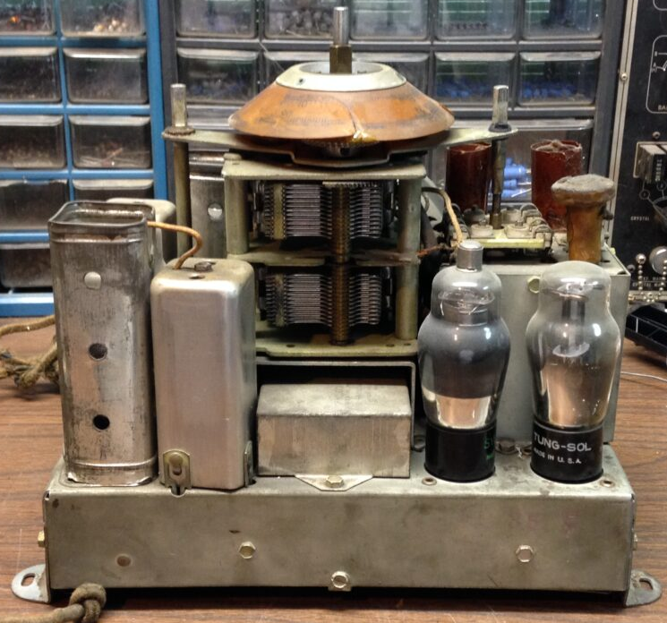
Back View
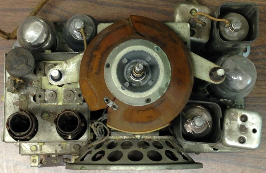
Top View
In case you are wondering the differences between the 604C and the later 37-604C, they are as follows:
- The 604 uses standard base tubes. The 37-604 uses octals.
- The 604 only has a three-screw terminal strip providing connections to a longwire antenna as well as two screws for Philco’s High Efficiency Aerial. The 37-604 has five screw terminals – two (RED and BLK) for Philco’s High Efficiency Aerial, one for ground (!), and two more used as “shorting” terminals. See the differences at the Philcoradio.com website:
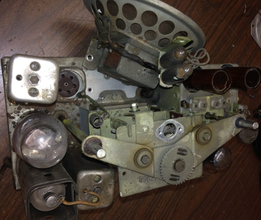
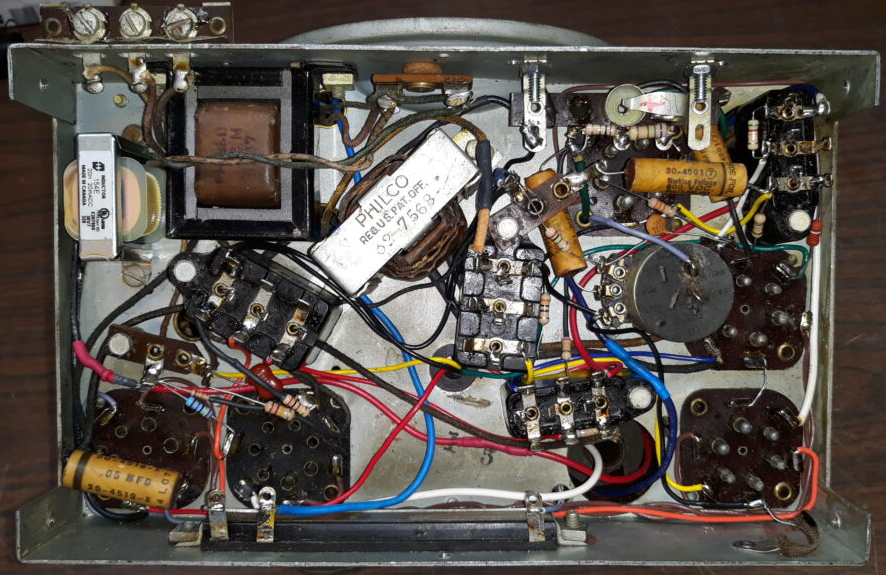
So I pulled the chassis out of the cabinet and dived in. Here is a look underneath.
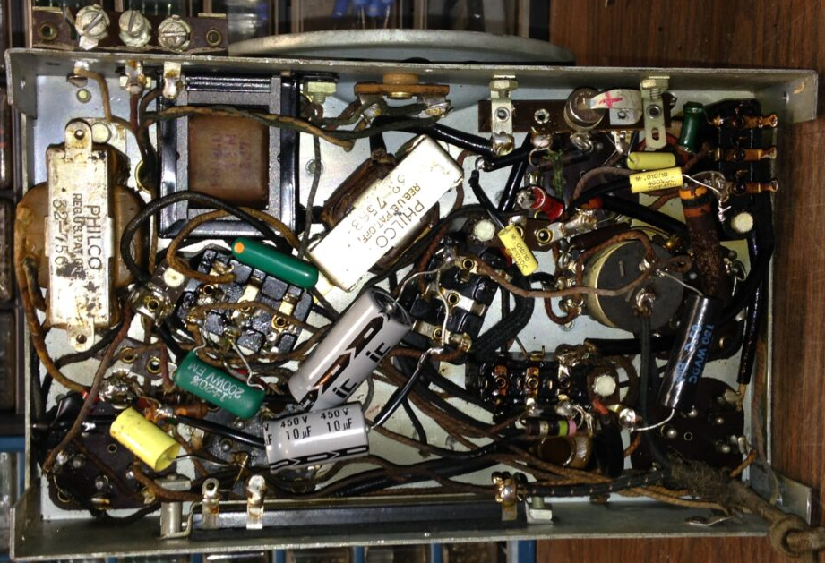
As you can see, someone else was in here before me. I will try to make this look neater than it does now.
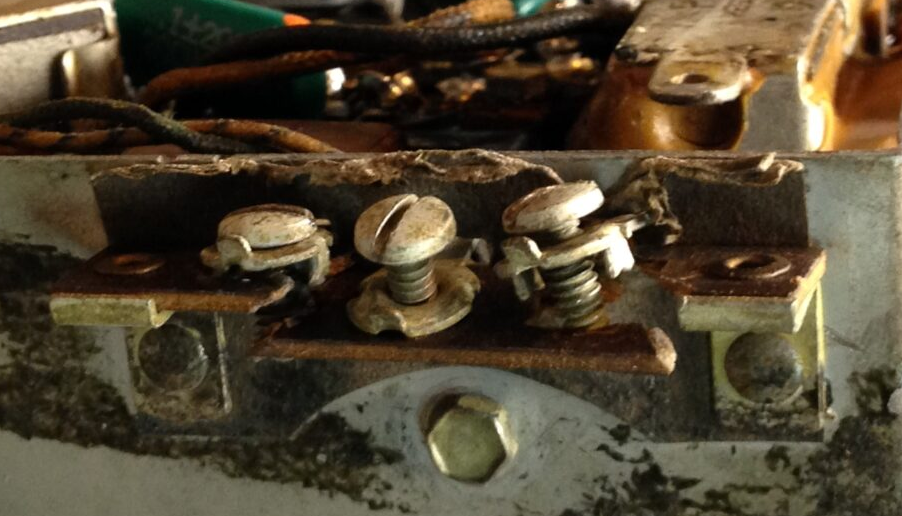
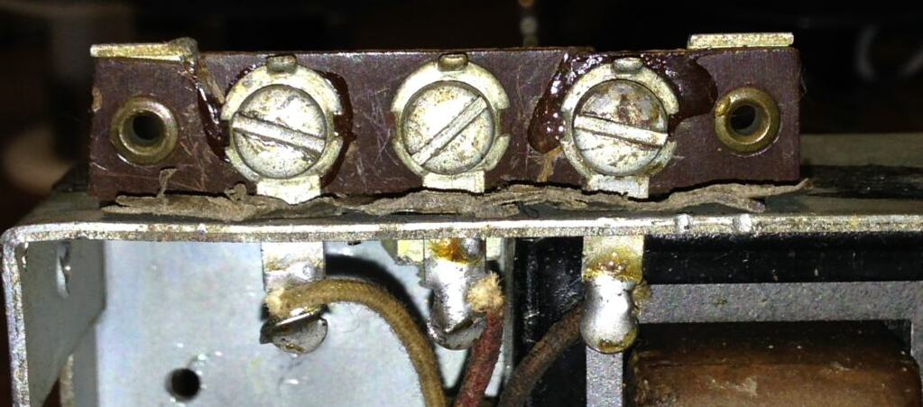
A closer look at the antenna screw terminals. As you can see, the terminal board is broken.
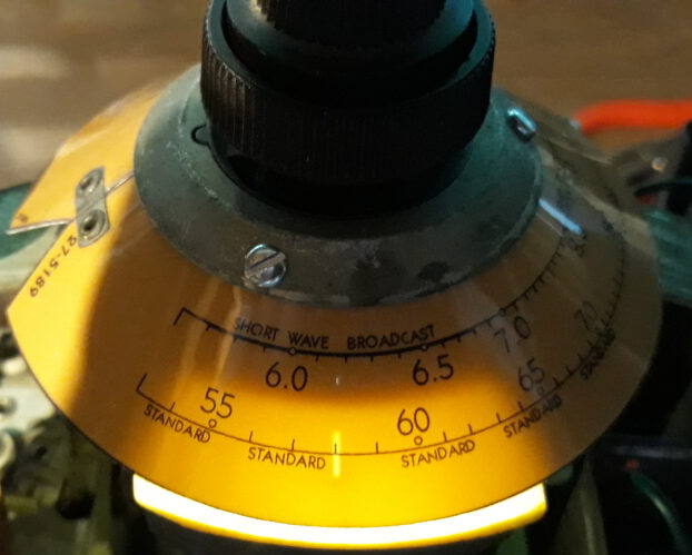
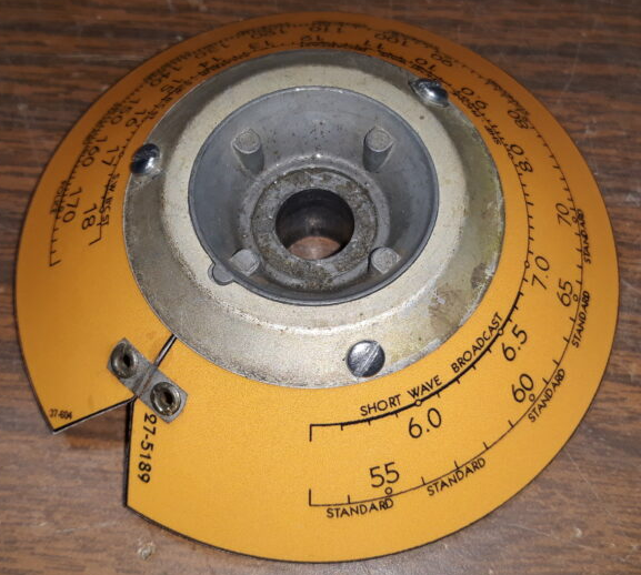
Now let’s take a closer look at the dial scale.
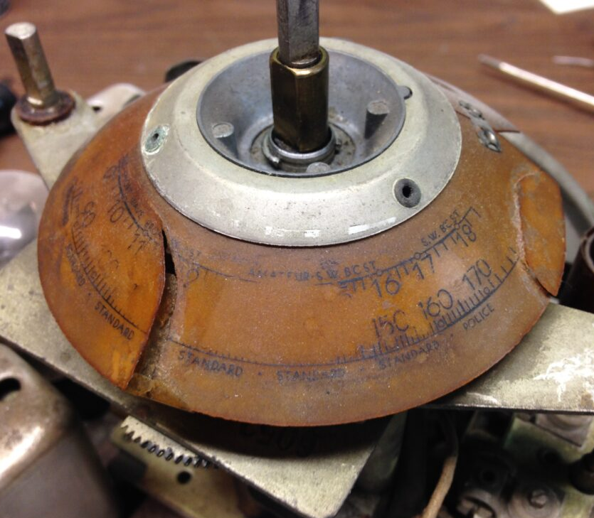
It is broken in two places, and part of the numbering is worn off. Fortunately, Radio Daze sells a 37-604 replica dial scale. I had to purchase one for this set as a broken dial scale is not a good thing. And it is good that I did buy a replacement, as the original would continue falling apart as I worked on the radio.
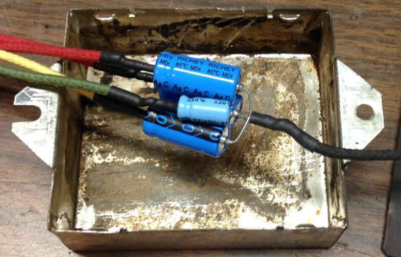
This set has its own unique RF unit which is a metal box that houses the band switch, three paper capacitors, and some wire. Coils are mounted on top of this unit, and there are also a couple coils inside.
If you think a 1937 Philco RF unit is difficult to service, just take a look at this:
That photo was taken after I had replaced all three paper caps. I did not bother to restuff the old paper caps in the RF unit of this set. It was difficult enough to get the old caps out and the new ones in without damaging anything.
After rebuilding all four of the bakelite block capacitors and replacing about 2/3 of the under-chassis paper capacitors and resistors, I decided to tackle the job I had been dreading: restuffing the metal can which houses the electrolytic capacitors. It is mounted underneath the tuning condenser, and is held in place by two bolts. One is easily accessible from behind the tuning condenser at the back of the chassis…
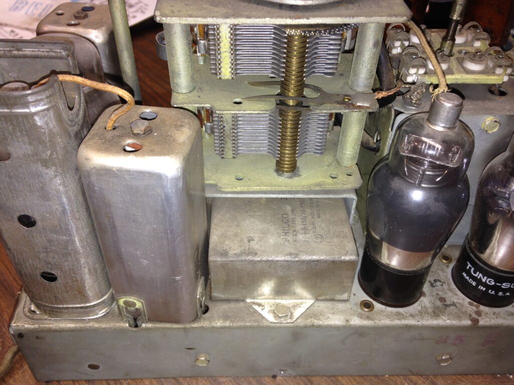
…and the other bolt is hidden by the speaker. Which meant that the speaker had to be unbolted and pulled out of the way.
To get to one of the bolts holding the electrolytic capacitor can, the speaker must be moved.
Once the speaker was moved out of the way, the other bolt holding the electrolytic capacitor can becomes visible – and accessible. Once the two bolts were removed, it was a matter of carefully pulling the electrolytic capacitor can out and away from the chassis.
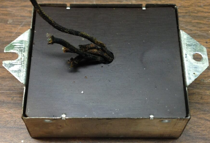
Here’s how it looked:
Someone had cut all but one of the wires, and had wired individual electrolytics under the chassis. I am going to stuff new electrolytics inside the original can, using new wires.
First, the original guts had to be removed. I unfolded two of the four tiny tabs holding the cover in place, and set it aside. Here’s what I found inside:
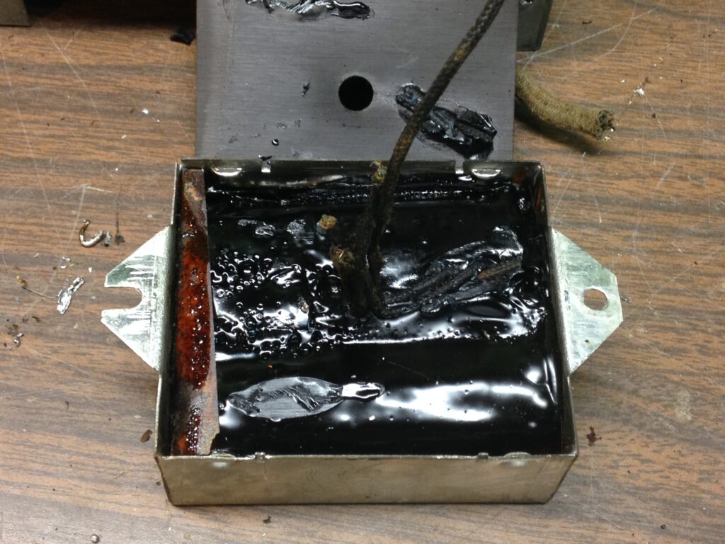
I was able to easily pry the old unit out of the can. Next, I prepared four new electrolytics to go inside the can. I added new wires to the four positive ends. All of the negative ends are connected to B- so all of the negative leads were twisted together and soldered to a black wire.
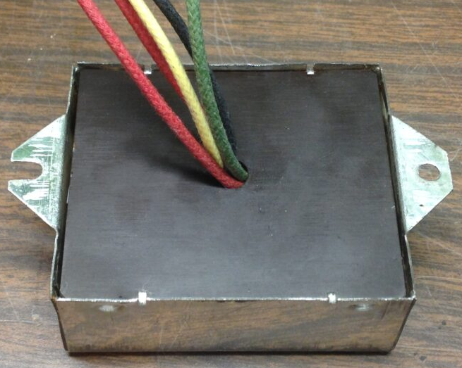
I then used some thick paper to make a new insulator to go inside the can, to help prevent anything from touching the chassis. I also taped up the exposed negative wires with electrical tape, so it should be fine. When finished, it looked like this:
This job turned out to be much easier than I thought it would be. It was no big deal to remove the two bolts holding the speaker and to move the speaker aside enough to get to the other bolt holding the electrolytic can in place.
I used the same colors for each electrolytic capacitor wire as called for on the 604 schematic.
The next order of business was to rebuild the dial lamp socket assembly (two sockets on a common bracket). The barrel-shaped parts that hold the lamp in place had both broken off at the bracket, so I glued them back together. I used heat shrink tubing to replace the old plastic insulation that had surrounded each socket, and installed two LED lamps.
I fixed the antenna terminal board with some clear epoxy.
Repaired Antenna Terminal Board
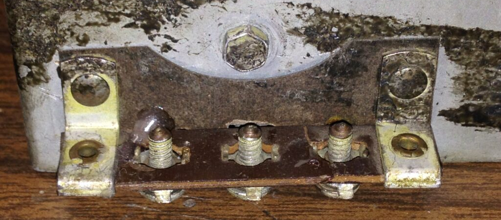
Repaired Antenna Terminal Board, top view
I tried the radio out. Unfortunately…no joy. The dial lamp and all of the tube filaments lit up as they should have, but there was no sound save for a very faint hum. Tubes were tested. The 6A7 and the 43 were weak. I replaced the 6A7. I did not have a spare 43 so it stayed.
There was no improvement. Plate voltage at the 75 and 43 tubes was normal. Placing a finger on the 75 grid cap results in a hum that was so weak, I had to put my ear up to the speaker to (barely) hear it with the volume control at maximum.
The radio now produced a louder hum at the grid cap of the 75 tube (I think it should have been louder still, but at least it was an improvement). It received nothing. No AM noise. No static. Nothing.
I plugged the 604 into an isolation transformer and started to hook up my signal generator. But when I attached the ground lead of the signal generator to the chassis (as the Philco specs call for), the GFCI which protects the basement outlets tripped. So much for that idea.
Next, I took some more voltage measurements, and made a startling discovery. There was no voltage at the plate of the 6A7. No voltage on its screen. No voltage at the oscillator “plate”. What the heck?!?!?
The problem: Choke (59), 2250 ohms, was open. This killed B+ to the det-osc and IF tubes. No wonder it wouldn’t work! Looking around in my stash o’stuff, I found a 2200 ohm chassis mount resistor. 50 watts, which was overkill. But hey, I had it so I tried it. It worked and the radio started to pick up a few stations. However, the volume was very low.
I tried feeding an audio signal from the computer at my workbench. Audio was very low and distorted. I then tried disconnecting the 604’s speaker voice coil lead and connecting a test speaker. Audio was very low and slightly distorted.
Then I remembered my Eico 147A signal tracer. This signal tracer allows you to use its output transformer and speaker as a test speaker with output transformer…and the signal tracer does not have to be on to perform
this test. (A good thing, because both the signal tracer and the 604 are AC/DC…and the two connected together and powered up would certainly cause the GFCI in line with my basement outlets to trip.)
I disconnected the plate leads from the 43 tube. I then connected the signal tracer’s output transformer to the 43 plate and to B+.
The 604 played loud and clear. So, a bad audio output transformer seemed to be indicated. But after replacing the audio output transformer with one from a Philco 37-602, audio remained low.
This is where, looking back five years later, I made a stupid decision (in my opinion). I decided to gut the chassis (except for the RF section) and rebuild it to match a Philco 38-14. Less parts, simplified circuit. What could go wrong? Well, nothing, really, except the radio would no longer have its original design.
And after doing all of that redesign/modification work, guess what? The radio still did not work correctly. Volume was still lacking. So, the chassis was put back into its cabinet and the whole thing was put back on the shelf.
Five Years Later…
Every once in a while, I would look at the non-working 604 as it sat on the shelf and would say to myself, I really need to pull that down and try to fix it again. In late summer 2020, as I recovered from a second cancer surgery, I decided it was time to revisit the 604.
I gutted the chassis (except for the RF section) again. I completely rewired the chassis to the original 604 specifications, using all new wires. I even went to the trouble of stuffing four paper capacitors so it would look sort of original underneath.
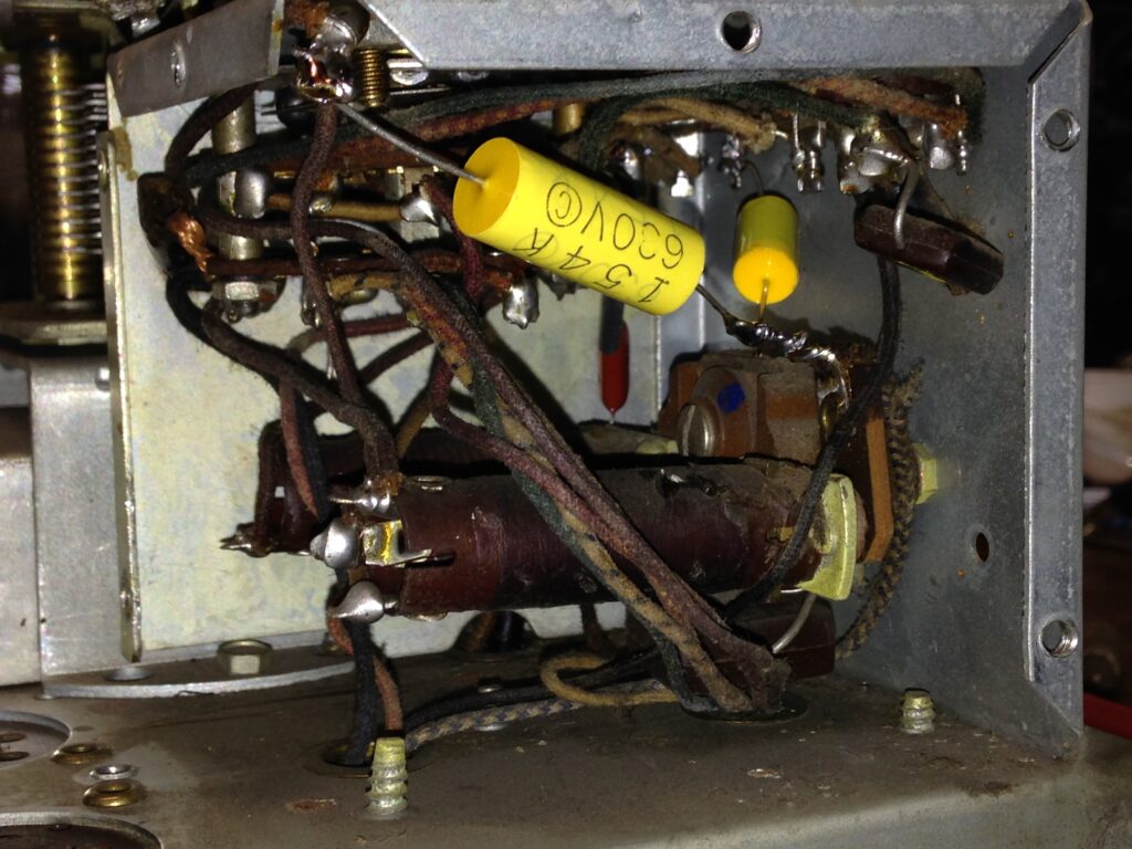
That 2250 ohm choke had to be replaced. The original specs were 65 H, 10 mA. I conferred with a friend of mine who happens to be an electrical engineer. He recommended a Hammond 154E (20 H, 1660 ohms, 20 mA) with a 580 ohm resistor in series, and to bump up the value of the input electrolytic capacitor a bit to take care of the possibility of added hum due to a smaller choke being used.
I followed his advice and increased the input electrolytic from 10 to 22 uF. This called for the electrolytic box to be restuffed again. I took advantage of the situation by using all new Nichicon electrolytics this time, with the exception of the 10 uF, 50 volt electrolytic used at the cathode of the 43 output tube. This small electrolytic remained a blue “no name” since I had several. They had been purchased from Mouser Electronics a few years ago. Since Mouser is a large supplier of quality parts, I wasn’t worried about the 10 uF, 50 volt electrolytics.
When my work was done, the underside of the chassis looked like this:
Underneath chassis of rebuilt Philco 604
It was now time to replace that dial scale. I finally opened the package from Radio Daze that had been sitting around for five years to discover that this dial scale was one of their older stock, laminated dial scales instead of their newer, higher quality silkscreened scales.
New dial scale in place on chassis
New Radio Daze laminated dial scale
Unfortunately, I was stuck with it so I used it. It was a bit difficult to install, so the laminated dial scale did have an advantage here. A silkscreened phenolic scale would have been much harder to install and could be easily broken.
Once the dial assembly was reinstalled, I discovered that the tuning mechanism would not tune smoothly with the C clip installed which holds the dial assembly in place. The solution was to leave the C clip off – this resulted in very smooth tuning.
I tested the tubes again as I had forgotten that I had tested them five years earlier. It is a good thing I did, as I found that both the 78 IF tube and the 43 output tube had heater to cathode shorts! I have extra 78 tubes so a replacement was no problem. I had to do some digging for a replacement 43, however. I just happened to find one. Whew!
The radio now worked as it should. Volume was fine, no problems. And there was no noticeable hum! The heater to cathode shorts in the 78 and 43 tubes were likely causing my volume issues all along.
After an alignment, the chassis was placed back into its cabinet.
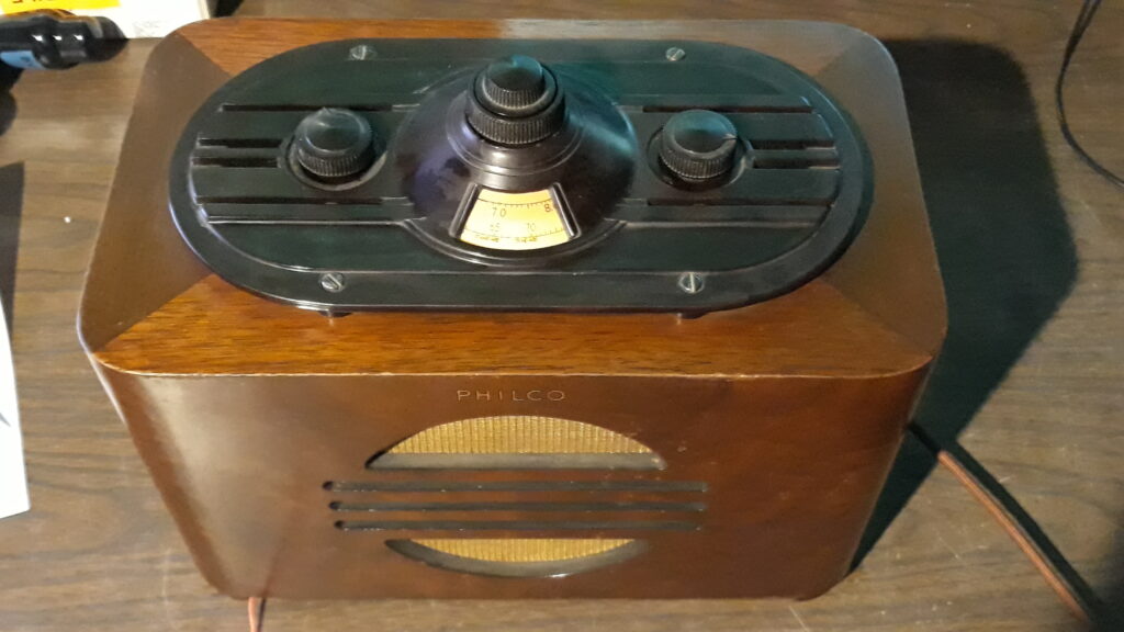
Completed Philco 604C, top view
The radio looked good and played well now. I still had one more thing to address it seemed that the entire tuning assembly was now sitting a bit too high. The new dial was rubbing up against the Bakelite at the top of the cabinet. As a result, the inner fine tuning knob did not work with the radio assembled in its cabinet. I felt that if I pulled the chassis and added some washers between chassis and cabinet, that these would take care of that dial clearance issue.
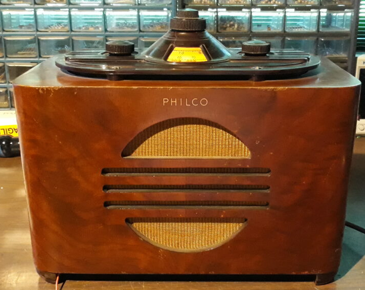
Completed Philco 604C
Final thought: I wish I had another Eico 147A signal tracer. For years, you could find these at swap meets for anywhere between $10 and $40. They are now selling for crazy money on eBay ($100+). Maybe because of everyone staying home due to the ‘Rona? I made a copy of the Eico 147A manual before letting the tracer go, and I may just build myself a replica one of these days, eliminating the wattage measurement function and building it strictly as an audio/RF tracer. By eliminating the watt measuring function, one could build a replica for less money than these are selling for now.
UPDATE 9/23/2020: I pulled the chassis out of the cabinet again and added some white lithium grease to points on the tuning assembly, and made sure the dial assembly was positioned as far down on the radio as it could be. When I reinstalled the chassis in the cabinet, I did add a washer between chassis mounting points and cabinet at all four mounting points. Doing these things completely cured the dial clearance and tuning issues and it tunes very smoothly now using either the outer (coarse tuning) or inner (fine tuning) knob.
UPDATE #2, 9/24/2020: I forgot to mention what I did about the bias cell. I bypassed it by connecting a 6.8 megohm resistor across the bias cell terminals, leaving the tiny battery out of the circuit. This gives enough bias voltage to the grid of the triode section of the 75 tube that no battery is needed, and the radio works well with this minor modification. The battery holder is still in place in case a future collector wishes to remove the 6.8 megohm resistor and reinstall a 1.5 volt battery.