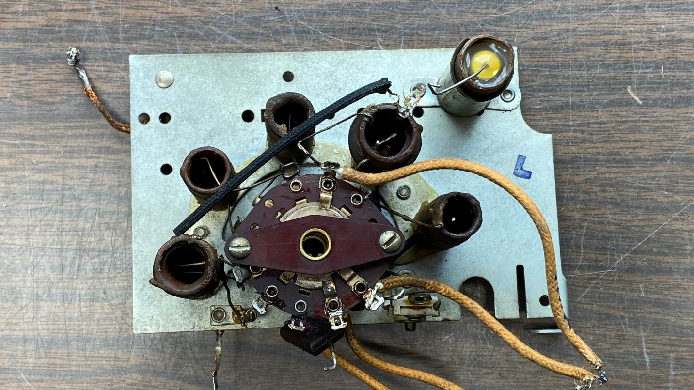
Ok. Time to tear apart the RF section and see if I can find that carbon track. I began by making a drawing of how things hooked up to the two switch wafers, C and D.
The stock hookup of wiring within the 38-690 RF section. 38-116 Code 125 is similar.
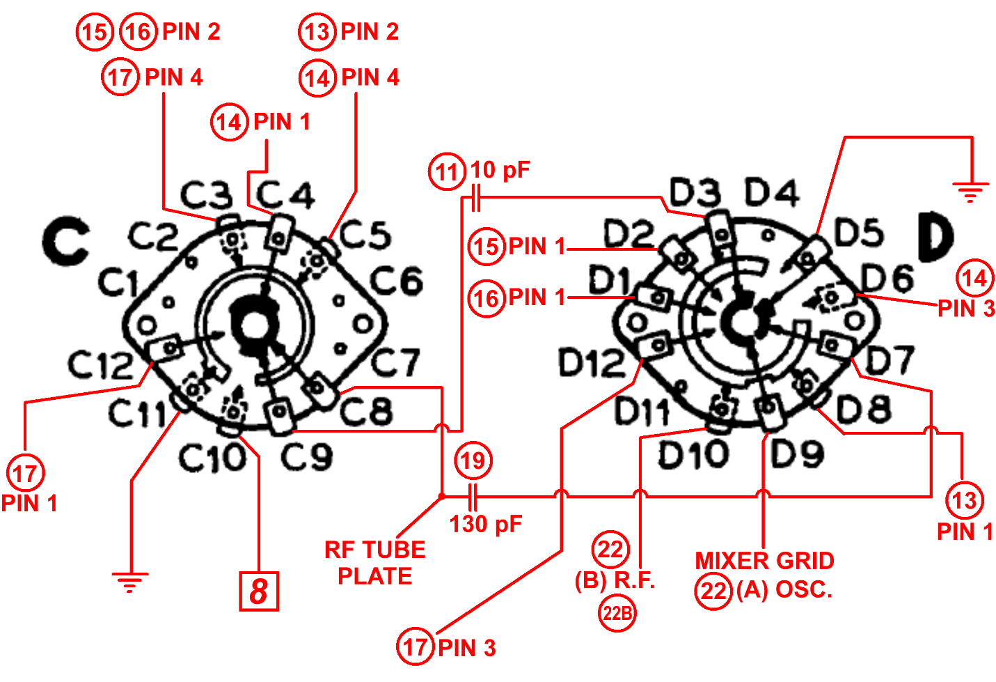
Next, I modified my drawing to reflect how I actually intend to hook things back up, in order to eliminate any ground connections to switch wafer C. Notice that switch terminals C3, C5, C10 and C11 will no longer be used.
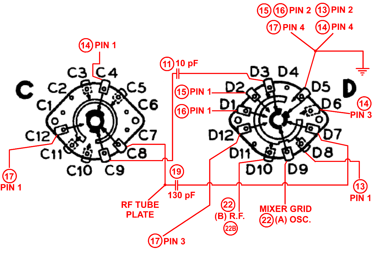
Modified hookup of wiring within the 38-690 RF unit.
Now, with plenty of road maps at my disposal, I began the process of actually disassembling the RF section. The 1937 Philco RF units are unnecessarily complex; by comparison, the 1938 RF units used for models 38-116 Code 125 and 38-690 are very simple. Perhaps too simple, really, with the exception of the awful wafer C design placing B+ voltage in extremely close proximity to ground potential. But as stated previously, I am going to change that when I reassemble everything.
I begin the process by removing mica capacitors (11) and (19), and the wire connecting to a grounding lug on the mounting plate. Also, a wire from the switch assembly to trimmer (22B) on the mounting plate must be removed. Now the switch assembly may be removed.
Separating the switch section from the mounting plate.
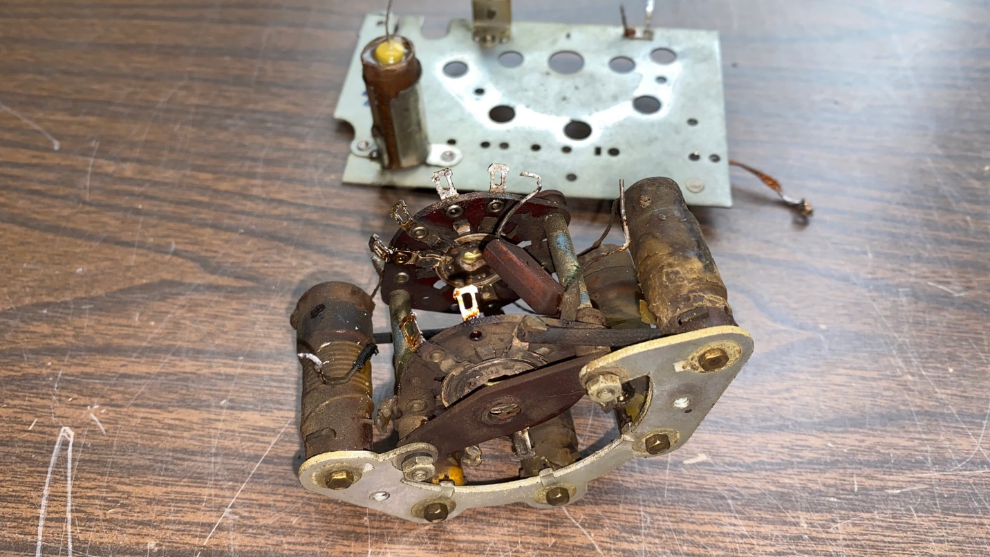
Once the switch assembly is removed, each of the five coils must be carefully removed. As I removed each one, I set each one aside, in order, so I would know which one would go where when it came time for reassembly.
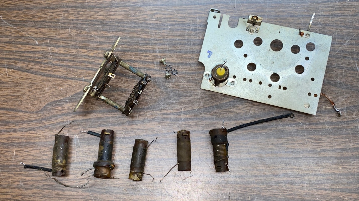
Once the coils are removed, only the switch assembly is left.
Now it was time to disassemble the switch assembly itself. Removing switch wafer D was easy and was soon set aside. Getting switch wafer C free of the hardware, unfortunately, was a different story. The long metal spacers on the screws are threaded, and they were very tight on the screws after not having been disturbed for around 83 years.
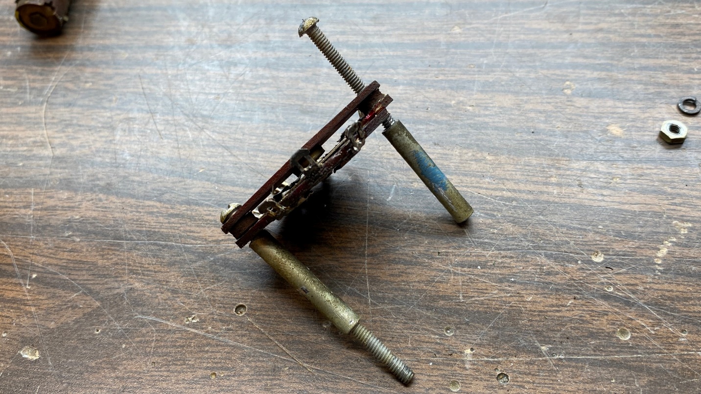
Attempting to disassemble the switch assembly. The spacers, which are threaded, are very tight and difficult to remove.
Working very slowly and trying to be careful, I managed to get one of the spacers unthreaded and removed. Unfortunately, about halfway through the second one, I slipped…and switch wafer C broke off at one end where the screw passed through it.
I swear that I could hear David Grimes laughing somewhere.
No matter that the wafer was now broken – I am going to replace it anyway. (I only hope that the parts unit is easier to disassemble.)
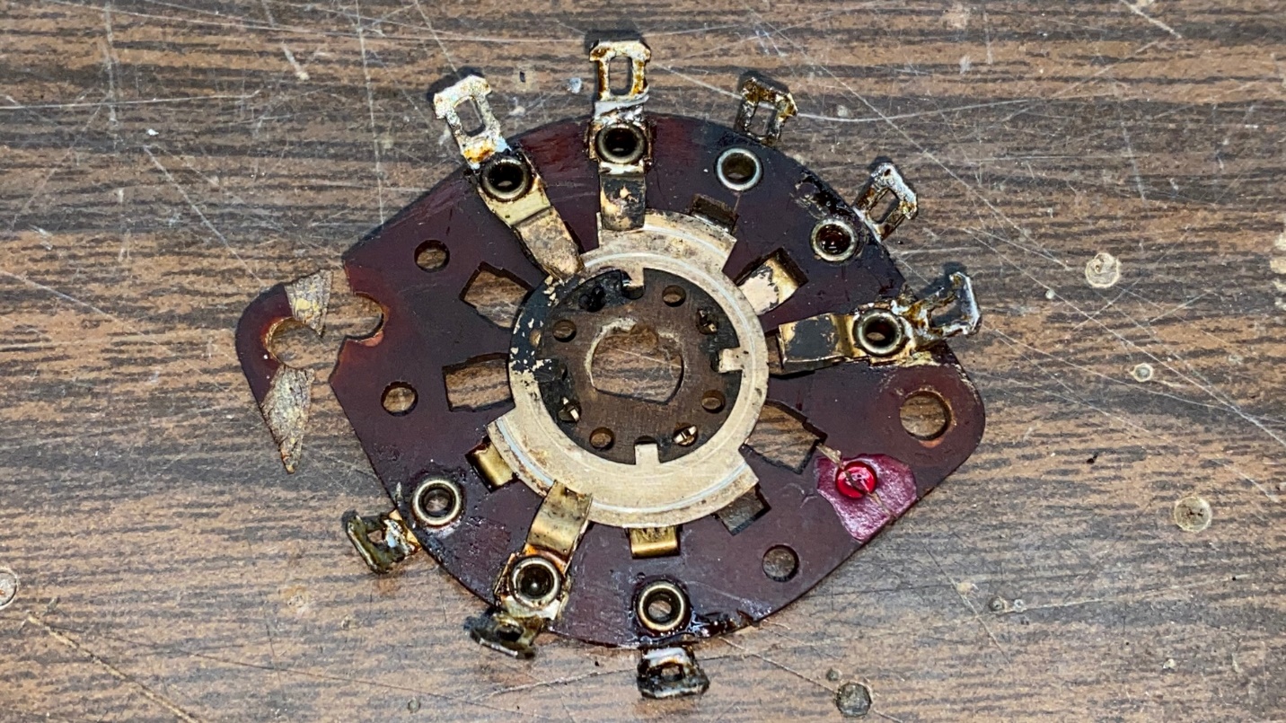
As you can see, switch wafer C (shown) was broken in the process.
Looking closely at switch wafer C, I saw no carbon tracks on the stationary portion of the wafer. However, I saw what appeared to be two small burnt areas on the rotary portion of the wafer. See the arrows pointing to these in the photo below.
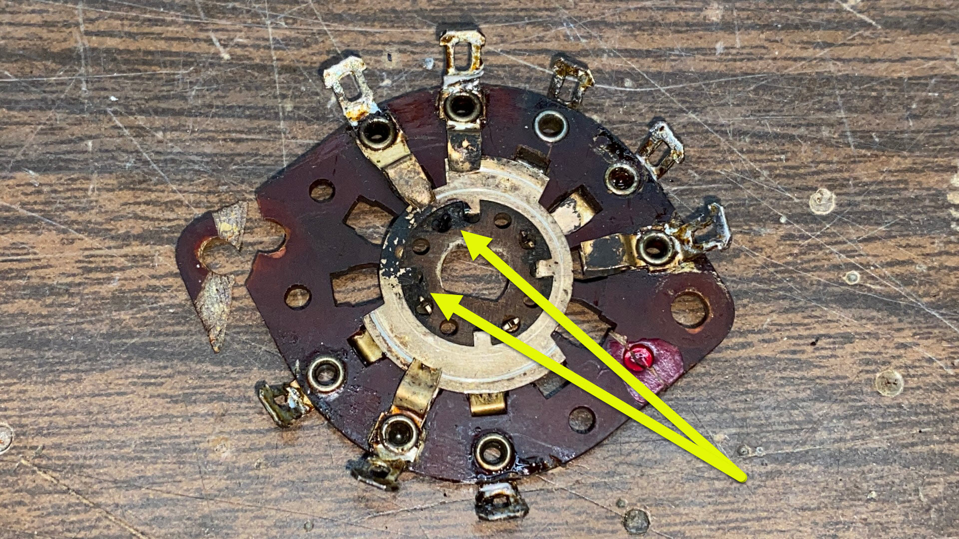
Arrows point to possible carbon tracks on the rotary portion of the switch wafer. This damage is not repairable.
In our next exciting installment, I will pull the RF section from a 1938 RF unit which is only good for parts, carefully extract its switch wafer C, clean it up (and the present switch wafer D) and prepare both for reassembly. Stay tuned.