Finishing things up.
In order to put the finishing touches on this chassis, I need to address the audio interstage transformer, replace and/or resleeve some wires which had been chewed by mice, perform some chassis cleanup, and reinstall the power transformer. We are getting close to being finished. So let’s go!
Audio Interstage Transformer, part (17)
The audio interstage transformer, part (17), must be unsoldered from underneath before it can be removed.
I began this time with the audio interstage transformer, part (17). It has an open primary. I am going to convert it to impedance coupling as described here.
Before starting, however, let us take a look at a partial schematic showing the model 65’s audio circuit.
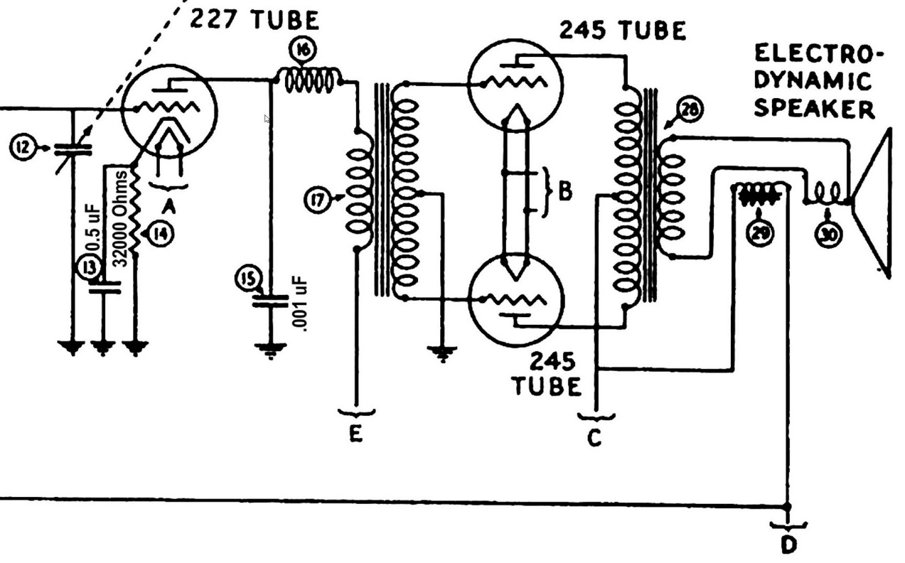
Original model 65 audio circuit.
The 227 tube is used as a detector. I am going to keep this part of the circuit original.
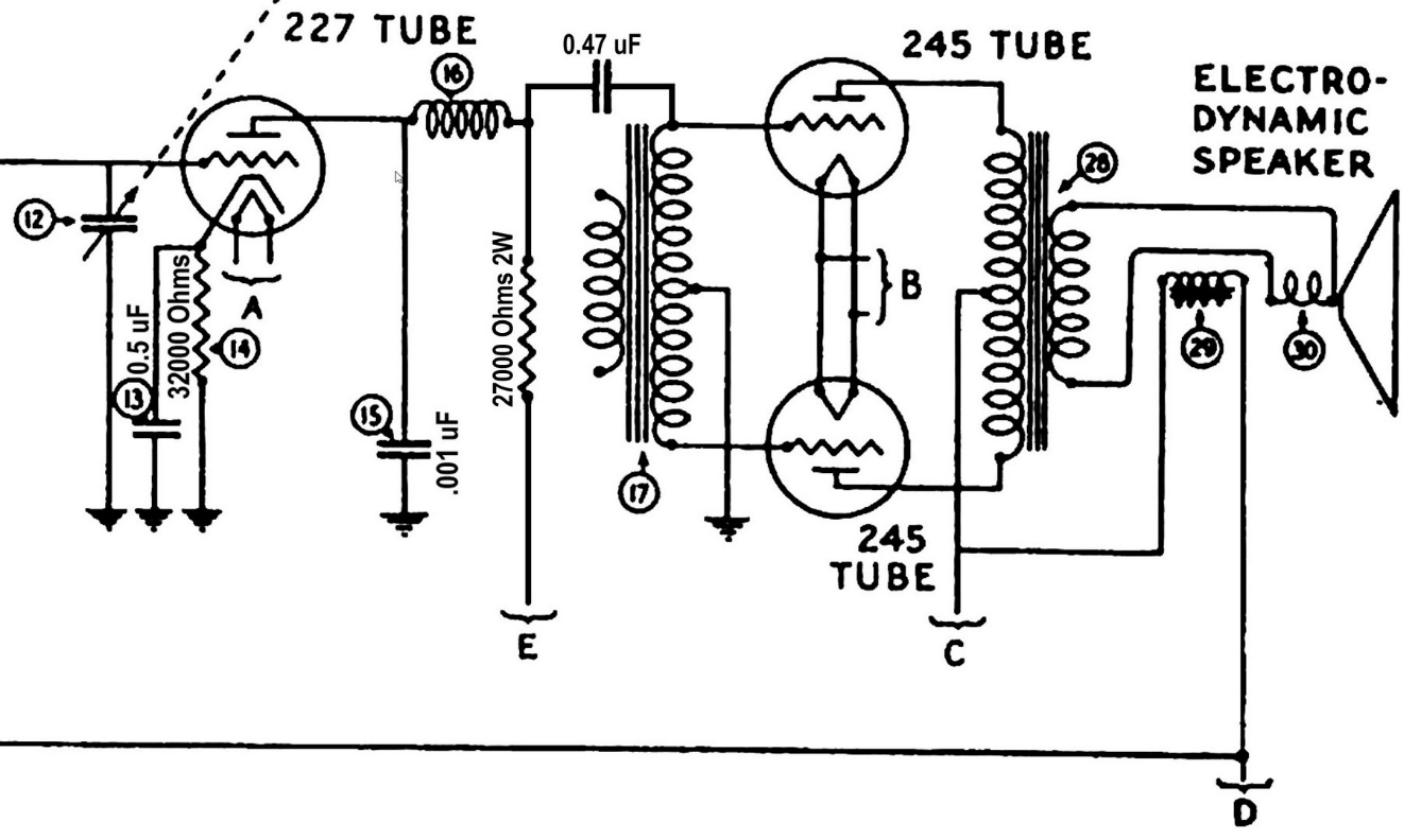
Proposed changes to model 65 audio circuit.
The output of the 227 detector is coupled through RF choke (16) into the primary of the audio interstage transformer (17). I am going to modify this portion of the circuit, adding a resistor in place of the open transformer primary, and a 0.47 uF capacitor to couple the audio signal to the push-pull secondary winding, which is still good.
I removed the transformer from the chassis after unsoldering and removing its wiring underneath. Then I carefully opened it up by removing the brass rivets at each mounting bolt hole. It was also necessary to unsolder the transformer leads from their respective terminals.
Once this was done, the bottom cover of the transformer (which also has the terminals staked into it) could simply be lifted off.
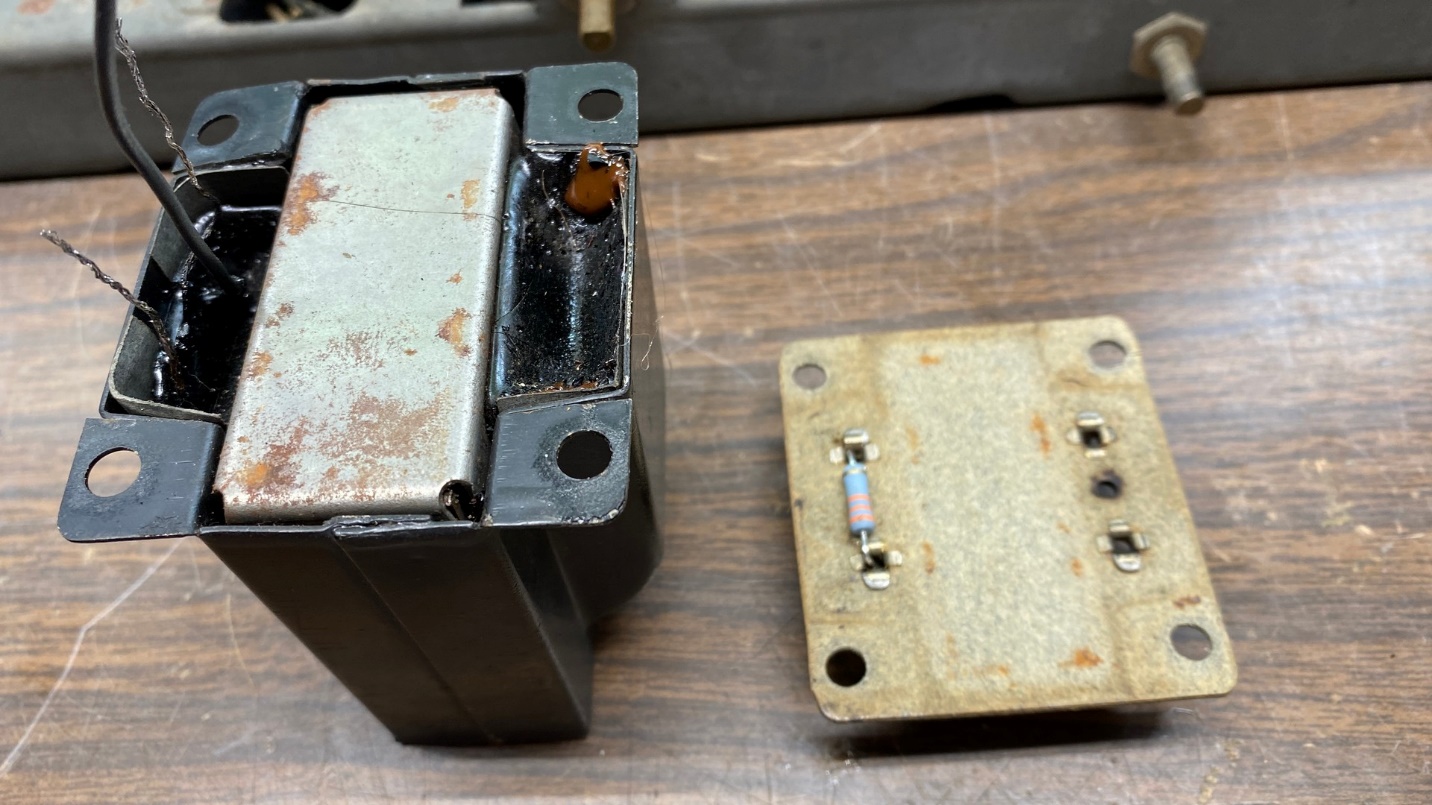
Model 65 audio interstage transformer, part (17), with bottom cover removed. Notice a new 33K, 2 watt resistor has been installed across the transformer primary terminals.
I cut off the primary leads since they were open anyway, and therefore useless. I added a bit of hot glue over each cut end to ensure the old primary would be completely out of the circuit. Next, a new 33K, 2 watt resistor was added across the primary terminals of the transformer.
I did not have any 27K, 2 watt resistors, and I forgot to order any when I placed my last Mouser Electronics order. Oh well. I will try to remember to get some 27K, 2 watt resistors the next time I order parts from Mouser.
The center tap lead had rubber insulation, and this was deteriorating. I carefully removed the old rubber and used a piece of heat shrink tubing to replace the rubber insulation.
Then, I carefully threaded each of the secondary leads through the proper holes on the bottom cover, after which I bolted the transformer back onto the chassis.
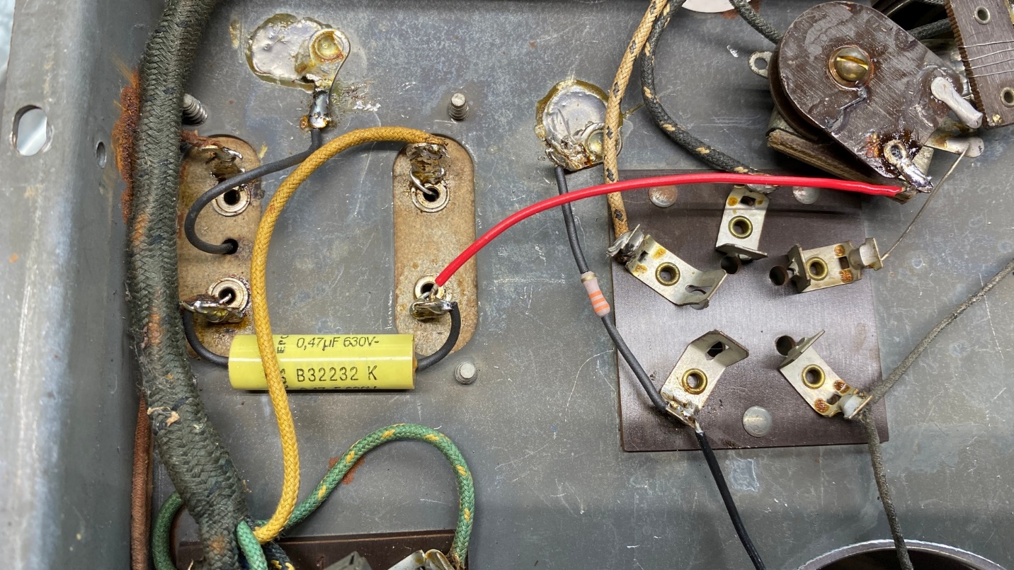
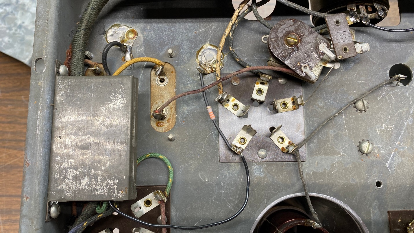
Part (17) has been reinstalled on the chassis, and wiring has been reconnected to it underneath. The 0.47 uF capacitor provides audio coupling to the transformer secondary as shown in the partial schematic above.
I soldered the two secondary leads back onto their respective terminals, and then reinstalled the connecting wires and resoldered these. As you can see below, I replaced one wire with a new red wire since the old one was not in the best of shape.
I added a new 0.47 uF capacitor under the chassis as shown above.
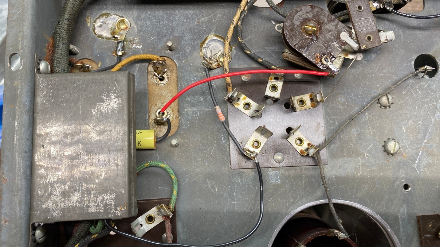
Finally, the metal can capacitor (13) may be reinstalled.
After everything was reconnected to the transformer and its secondary center tap was soldered to a nearby ground terminal, I reattached capacitor (13) to the side of the chassis as shown above.
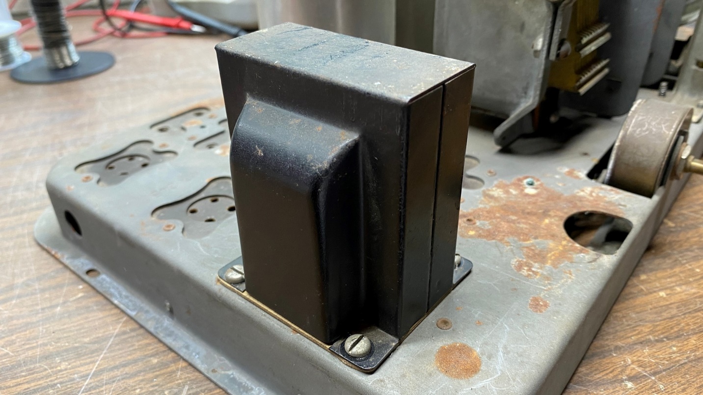
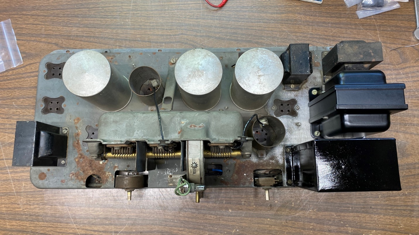
Audio transformer (17) back in place on top of the chassis.
Replacing and/or Resleeving Various Wires
Mice had chewed a few of the wires. It could have been worse. I might have ended up with an unusable wiring harness or, at the very least, multiple damaged wires. Fortunately, the damage was limited to only a few wires.
Part of that damage included the wires going from the wiring harness up to the dial lamp socket.
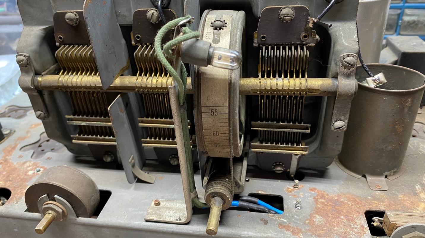
New wires leading to the pilot lamp were spliced to the originals at the bottom of the tuning assembly, as shown.
I unsoldered and removed the two original wires from the dial lamp socket and, one at a time, cut each wire close to the area of damage. Then I stripped the old wire at the point where it had been cut. Taking a new piece of cloth-covered wire, I cut it long enough to reach the dial lamp socket, stripped one end and made a mechanical joint with the old, stripped wire by wrapping the ends together and then soldering them. Finally, two thicknesses of heat shrink tubing were added to insulate the splice. I then repeated the procedure for the other dial lamp wire.
When done, the other ends of the wires were stripped and soldered to the proper terminals on the dial lamp socket.
I replaced a few wires which connected some of the tubular capacitors together. The center tap of the volume control (25) also received a new wire between it and capacitor (9).
A blue wire which connected to the speaker socket had one small point where the insulation was damaged. Here, I added two layers of heat shrink tubing to sleeve and insulate the damaged insulation.
The two 224 grid cap leads were rubber-covered and hard as stone. Both these wires were replaced.
There is a rubber-covered wire between coil (7) and the 1st RF tube socket which is threaded through a braided metal shield. I unsoldered each end of the wire, carefully removed it, and then installed a new wire through this braided shield, soldering it to its respective terminals on each end.
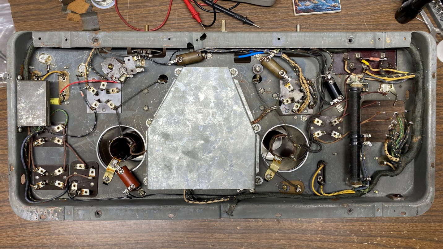
Other than reinstalling the power transformer, work underneath the chassis is complete. The wires that had been chewed by mice have been replaced or sleeved with heat shrink tubing, as appropriate.
Oh, by the way, all three coils tested good!
Once finished with the wiring repairs/resleeving, I reattached the center shield under the chassis as shown above.
Reinstalling the Power Transformer
I decided to repaint the bells (outer covers) of the power transformer as it looked fairly rough. After a few coats of Krylon Semi-Gloss, the transformer looked like new.
The process of bolting the transformer back onto the chassis was straightforward. After the transformer was back in place, I resoldered all the wires back to the proper terminals. This job took less time than I thought it would. My notes were a great help during this process.
While I was at it, I decided to replace the wires which ran from the power transformer to the 80 socket.
You can see the results below.

The model 65 power transformer is now reattached to the chassis and all connecting wires are reconnected.
I did not run the primary leads of the power transformer under any of the other wires, because it would have made reconnecting these leads very difficult. Instead, I took the easy way out and left them as you can see above.
I installed a new cloth-covered AC cord, 7-1/2 feet in length, along with a vintage AC plug on the far end.
Originally, the factory used rubber tape and friction tape to cover the splices in the wires of the primary leads, the wires from the power switch, and the leads of the AC cord. Now, each splice has two thicknesses of heat shrink tubing. I feel the heat shrink tubing is much safer.
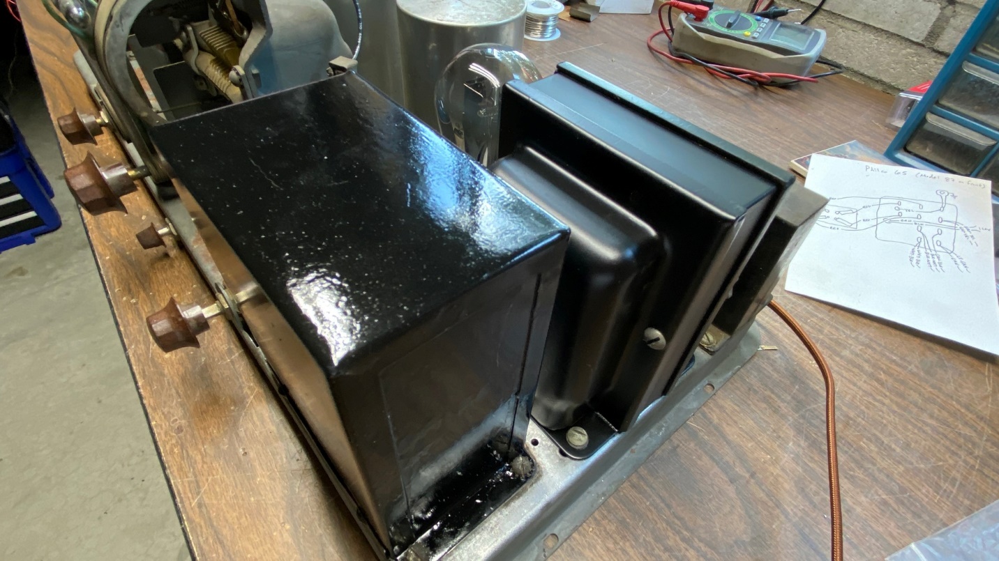
The rebuilt filter condenser can and the repaired power transformer, both back in place on the chassis.
Finally, I reattached the can (cover) of the filter condenser block to the bottom, and to the chassis.
I then tested the six tubes. Three of the six were very weak and were rejected. Fortunately, the three good tubes were also the most expensive – the CX-380 rectifier and the two CX-345 output tubes. A look in my tube stash soon yielded a UY-227 and two Arcturus Blue 124 tubes; these were installed in place of the weak Cunningham tubes.
By now, you can probably guess what comes next. Yes, I will try this radio out. But that will have to wait until next time. Stay tuned!