By now, the chassis was nearing completion and it seemed a good time to test the tubes. I had the tubes from the T9-10 chassis, along with most of the tubes from the T8-14 chassis. I had removed both sets of tubes and did not keep up with which tubes came from what chassis – not that it really mattered.
Testing the tubes found that some were bad, but enough were good to allow for an almost complete set in the T9-10 plus some leftover good spares.
Unfortunately, the 6E5 tuning indicator was one of the bad tubes and will require replacement. In addition, the T9-10 came with a 5Y3G which is an acceptable substitute for the original metal 5Z4 rectifier. I would like the set to have all metal tubes (save for the 6E5), since metal tubes are what were originally installed in this radio. So I shall need to contact my favorite tube supplier, FindATube.com, for a 6E5 and a 5Z4.
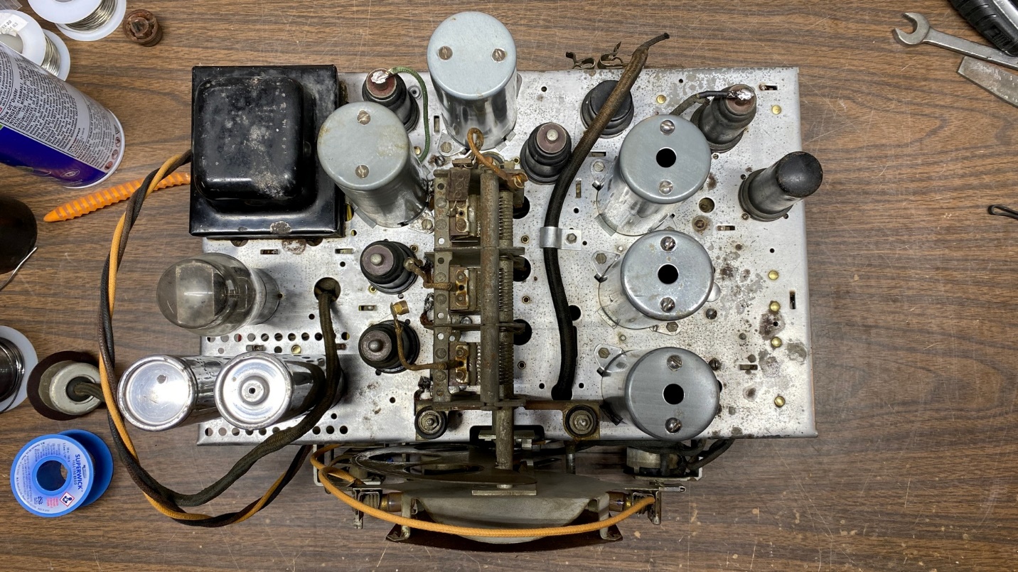
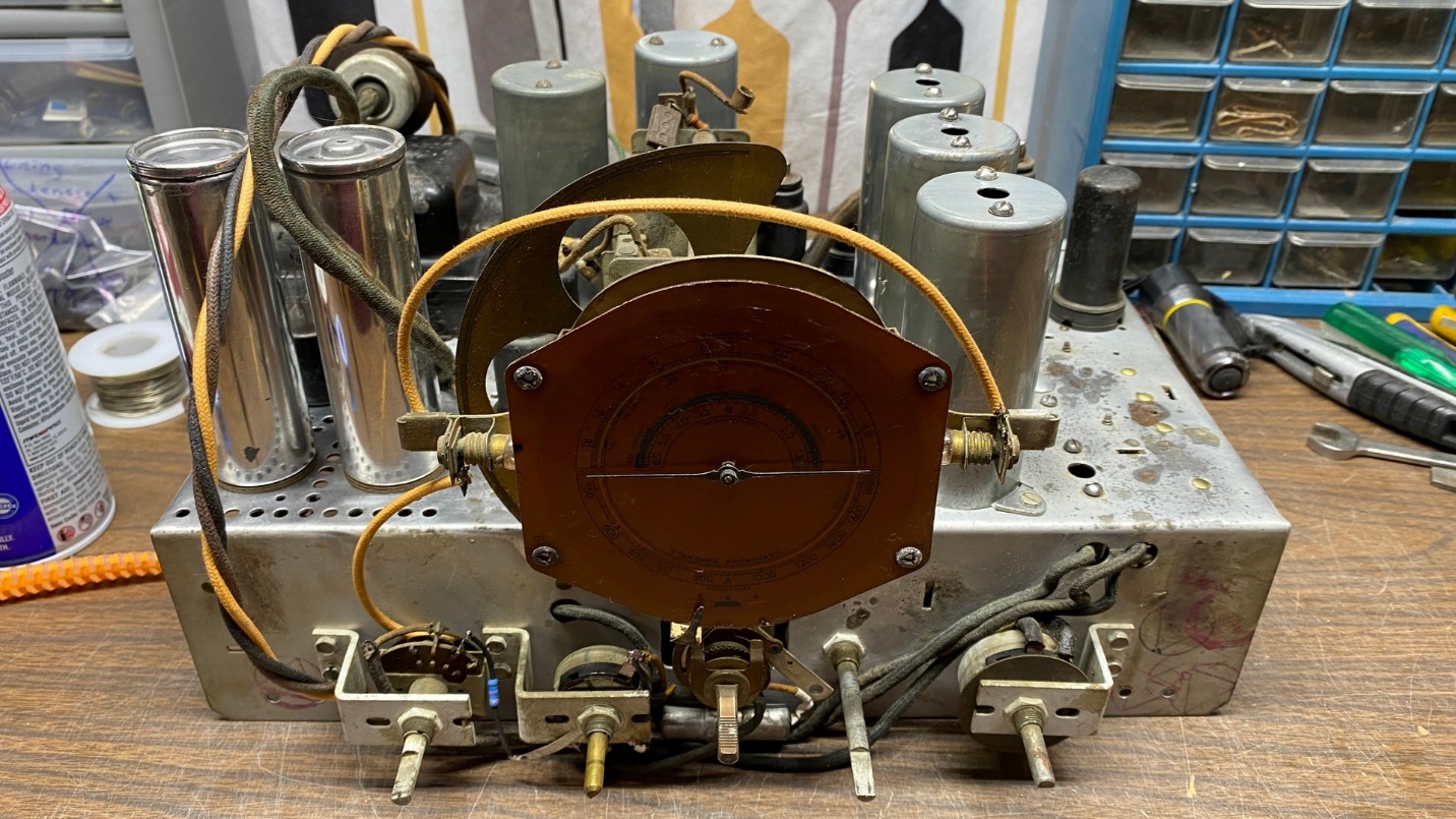
The top of the chassis looks like a complete radio chassis once again.
All work under the chassis was complete. All paper capacitors were restuffed with new yellow film capacitors, and leads lengthened as needed. All carbon resistors were replaced. All rubber-covered wiring was replaced with new wire with color-coded plastic insulation.
The photo below does not show the new power cord which I also installed.
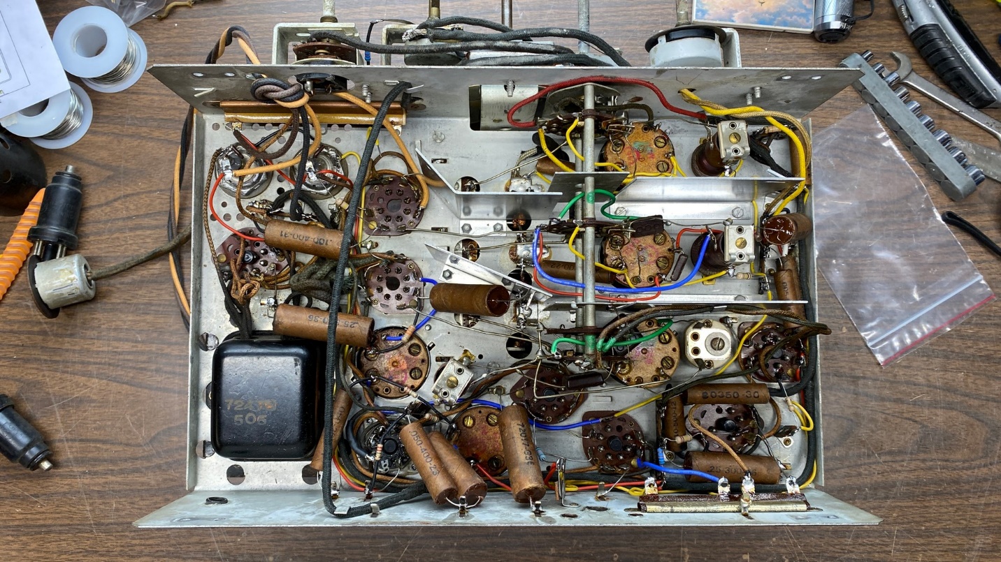
The work under the chassis is now complete.
Now, compare the photo above to how the underside of the chassis looked before work began back in late January:
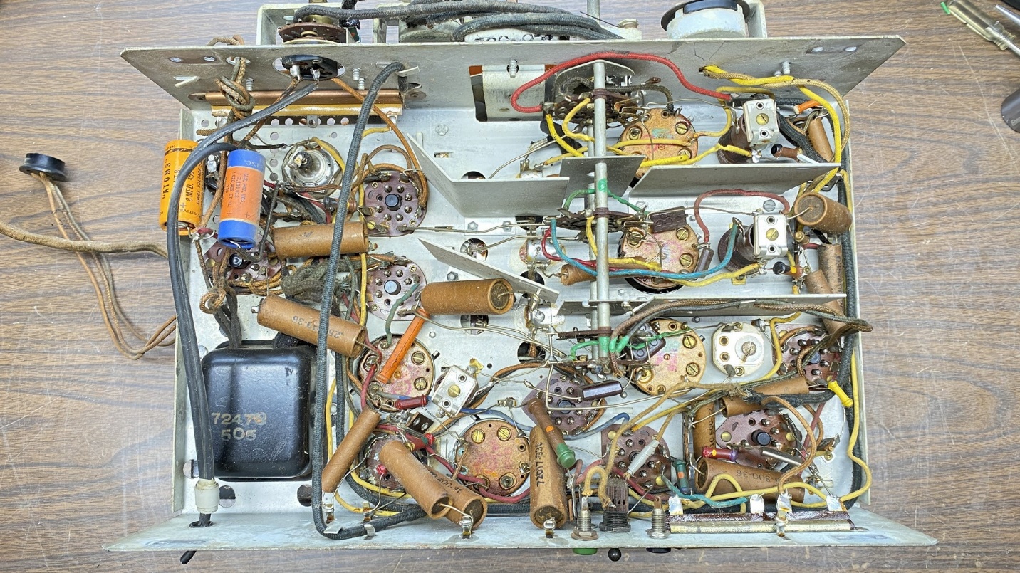
A “before” view of the T9-10 chassis as viewed from underneath.
There was yet one more detail to take care of before I tried the radio out, and that was replacement of the 1 megohm resistor located inside the 6E5 tube socket assembly. These old resistors are known to go bad over the decades, causing degraded performance of the tuning eye tube.
Of course, this radio is in need of a tuning eye tube as the original was bad, so there was no real hurry for me to do this. But I wanted to get this done while the chassis was still on the bench and not forget to take care of it later.
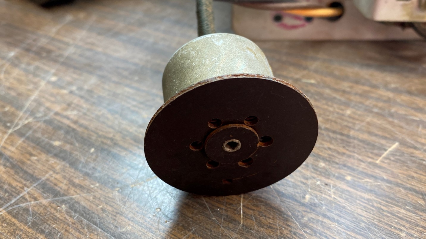
Let us not forget the tuning eye tube socket.
I had no idea how to remove the metal cover from the back of the eye tube socket. So, I tried twisting the cover clockwise, and guess what – it easily came loose!
The metal cover merely twists off to separate it from the phenolic socket.
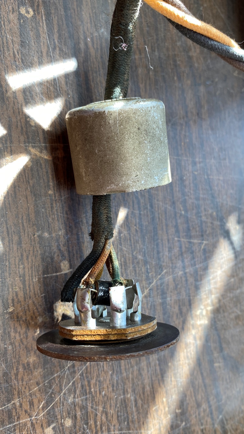
Pulling the cover back along the cable to give myself room to work, I soon had the tube pin contacts exposed and I could get to the two contacts where the 1 megohm resistor was soldered.
Some quick unsoldering allowed me to remove the old resistor. A new resistor was soon soldered in place.
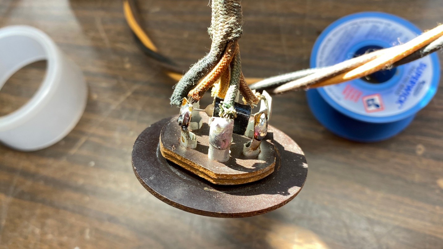
It is now a simple matter to unsolder and remove the old 1 megohm resistor, and replace it with a new one.
When finished. I slid the cover back over the back of the socket and twisted it counterclockwise back into place.
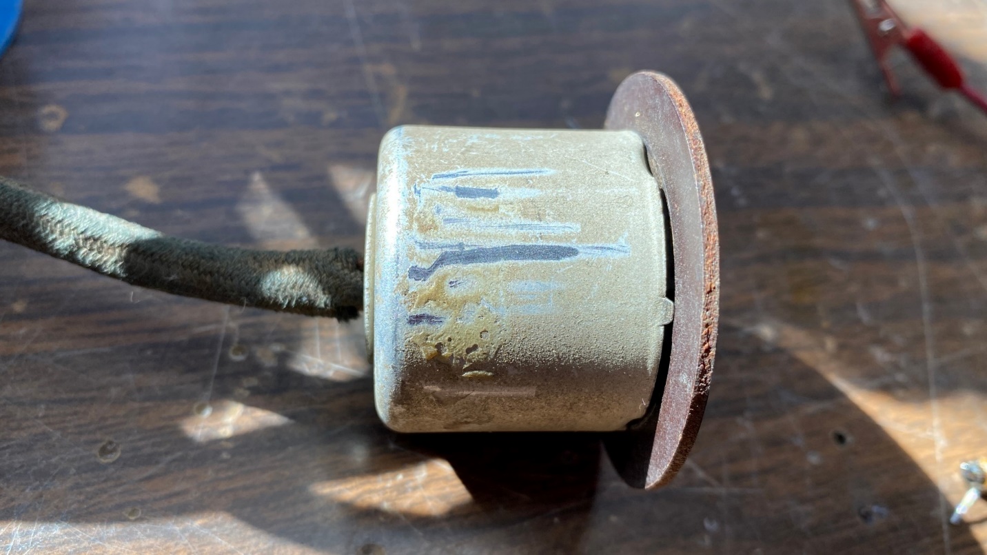
When finished, the cover twists back into place on the phenolic socket.
The time to try the radio out had come. I retrieved the speaker, which I had left bolted into the cabinet for safe keeping.
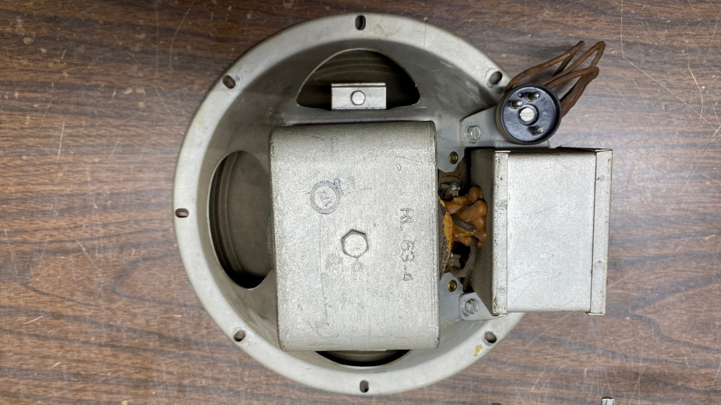
Evidence of wax leakage from the speaker field coil may be seen here.
I soon found that the speaker had issues. In the photo above, it is obvious that wax had leaked out from the speaker field coil at some point. I grabbed my digital multimeter and performed a resistance check of the field coil as well as the primary of the audio output transformer. Fortunately, both had good continuity. The resistance of the output transformer primary did not match published specifications, but I felt it was probably good enough for a test.
The cone (below) was torn in several places and would require reconing. This will be a job for Rich Stamer at Sound Remedy in New Jersey, who does excellent work on speakers.
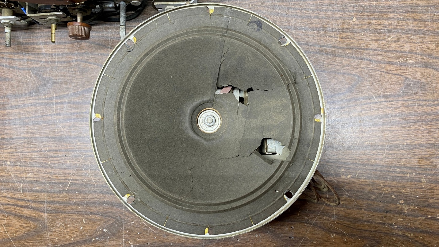
The cone is seriously damaged as well, and will require reconing.
I plugged the speaker cable jack into the plug on the back of the speaker. I replaced the dial lamps with LED replacement bulbs. I connected my longwire antenna to the radio’s antenna terminal. Then, I plugged the radio in and turned it on.
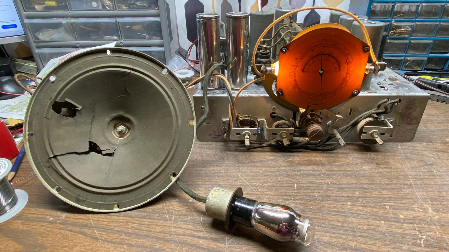
Trying the radio out for the first time.
Soon, I was able to tune in a few stations on the AM band as well as a couple on the high (band C) shortwave band. Band B (low shortwave) appeared to be dead. But the work had not been wasted – the radio was working!
I let it play for a while. The speaker field did not get hot; in fact, it did not even get warm! The same could be said for the set’s power transformer. All appeared to be well.
A few days later, I performed a complete alignment of the radio. I had recently purchased a second 20 dB attenuator for my function generator. I already had one 20 dB attenuator attached to it, yet it still seemed to produce signals of too high an amplitude for average radio work.
The alignment procedure revealed a problem – I was barely receiving the alignment signal on band B, and the band B antenna trimmer was unresponsive. This radio has separate sets of coils for its three bands. I performed a continuity check of the band B antenna coil, and found that its secondary was open.
This is where it comes in handy to have a parts chassis. Hopefully, the T8-14’s band B antenna coil will be good; and if so, it will be a simple matter of switching the coils and realigning band B. But we are out of time again, so we will have to find out next time if the coil from the parts chassis is indeed a good one or not. Until then!