Wrapping it all up.
It had rained the morning after I finished rebuilding the two Mershon condensers, but then the sun came out that afternoon. Not wanting to wait any longer, I found an old shoe box, cut round holes in its top just large enough for the bases of the rebuilt electrolytic cans to fit into, and took the box, the two Mershons, and a can of clear gloss lacquer spray outside.
I set up my folding work table, placed the shoe box on the table, pushed the bases of both Mershons into the holes in the shoe box lid, and then gave both cans two coats of clear lacquer spray.
I checked on the cans an hour later, and found that both had taken on a whitish appearance. Obviously, it was too humid outside thanks to the morning rain. However, this was not a problem – I simply went in and grabbed a can of Mohawk No Blush Plus. This product is designed to eliminate the “blushing” or whitish appearance of lacquer when it is sprayed in humidity that is too high.
A quick coat of No Blush Plus on both cans immediately eliminated the blushing, and the cans then looked as they should.
Later that day, I brought the shoe box inside (with the cans still attached to the lid) to dry overnight.
The next day, I attached the positive terminals (L-shaped pieces of metal) to the positive studs of both Mershons, using a lockwasher and a second nut on each.
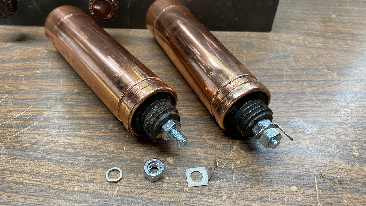
The positive terminal has been reattached to one Mershon, while the other awaits its turn.
Once this was done, I rubbed some 400-grit sandpaper along the bottom lip of each Mershon, to make sure there was no lacquer to prevent the cans (which also serve as the negative terminal of the capacitors) from making good contact. Once this was done, both Mershons were attached to the Philco 90 chassis. After they were physically installed, they were wired back into the radio circuitry.
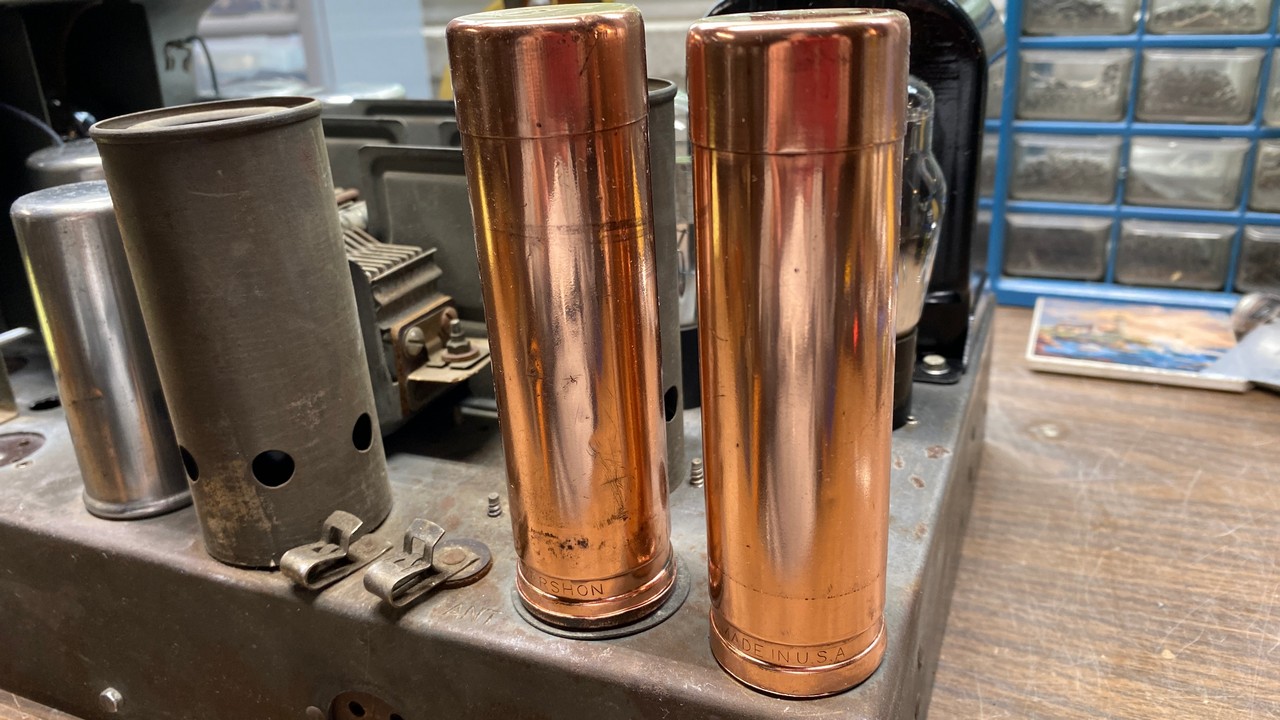
Rebuilt Mershon capacitors mounted on the Philco 90 chassis.
Unless one were to look very closely, the cuts in the bottom of each Mershon are really not noticeable. The cut on the left Mershon cannot be seen at all as the insulated negative terminal forms a “cup” which covers the cut area of this can.
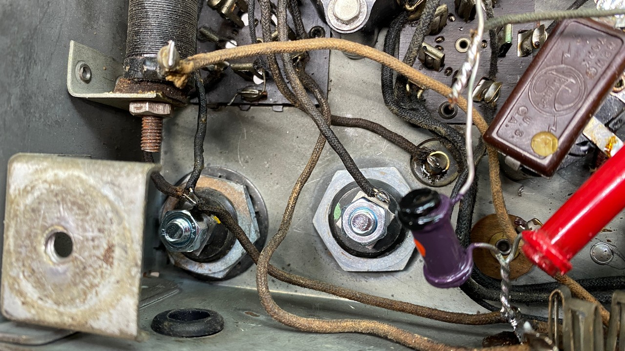
The rebuilt Mershons are now wired back into the radio circuitry.
Even though these are 8 uF Mershon cans, and not the original 6 uF units originally used, I am very pleased with their appearance. They certainly look better than the aluminum can electrolytics which someone had installed into this radio many decades ago.
To complete the electronic restoration of this radio, I only needed to install a new power cord. When I bought the Solen capacitors from Antique Electronic Supply, I also bought 50 feet of cloth-covered AC power cord.
This power cord is truly authentic – it not only has a cloth covering overall, but the two conductors inside each have cloth covering over a rubber insulated wire. This can be very difficult to work with. However, it should be treated as old-fashioned “push-back” wire. Simply push back the outer cloth, then push back enough of each inner cloth covering to expose the rubber wires. Strip the wires as needed. Cover the cut cloth braid with a little super glue; this will prevent the cloth coverings from unraveling.
I went to my stash of tubes in search of three type 24 tubes. (I had previously pulled out a globe 47, a globe 80, and two globe 27 tubes for this radio.) Unfortunately, I only had one globe 24, so it was installed in the IF socket as it would be easily seen from the back of the set. I found, and used, two taper-top or “ST” type 24A tubes. These were placed under the large tube shield, where they would be mostly hidden from view.
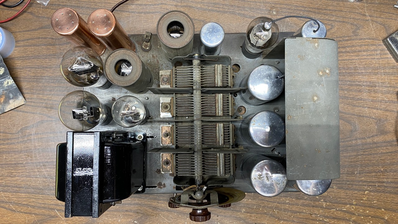
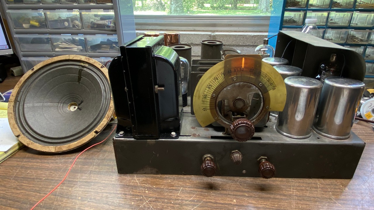
Top view of the completed Philco 90 chassis.
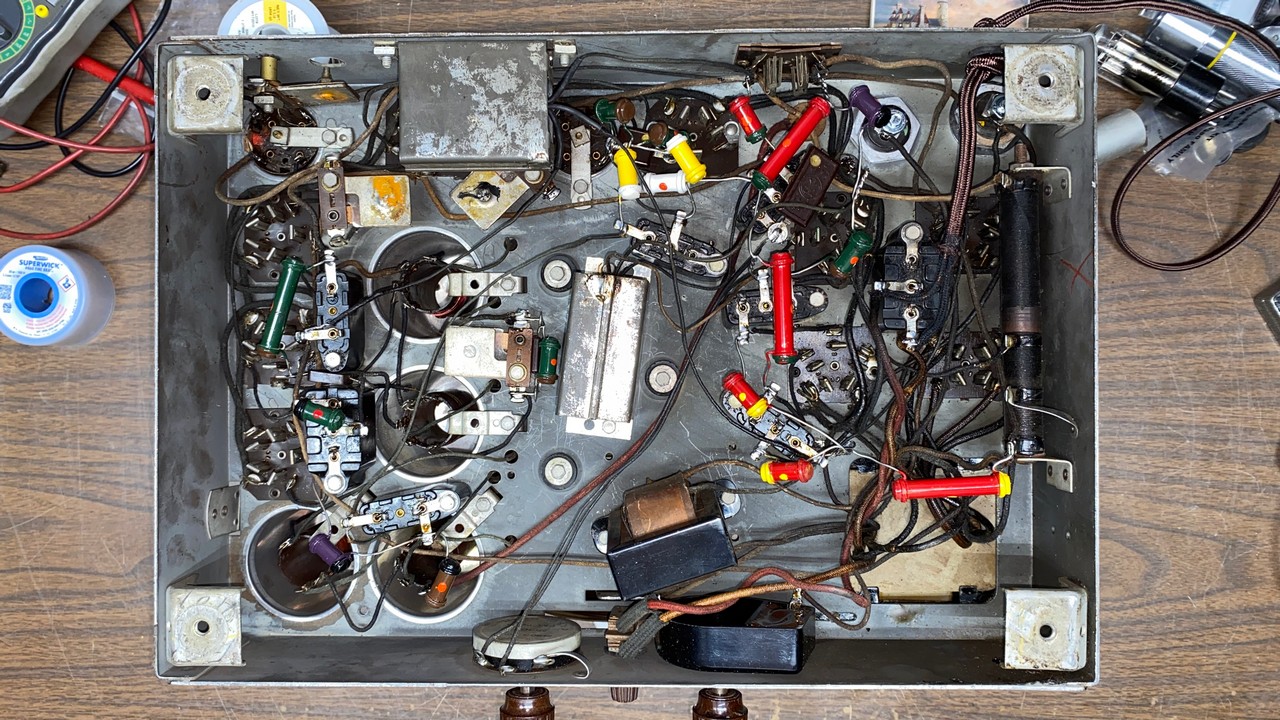
Bottom view of the completed Philco 90 chassis.
I think the only way this chassis could possibly look any better is if it had no surface rust, if the two individual 27 tube shields had new tin plating, and if I had not used that awful Rustoleum paint on the power transformer bells and shield! Overall, I think it looks great, though. I really like the under-chassis view, with those reproduction dogbone resistors.
The time had come. I had spent over a month on this chassis, and it was finally time to try it out and see if all that work was going to result in a working radio. I retrieved my test speaker, which had been given to me by a good friend several years ago and was designed for testing Philco 70 and single-47 Philco 90 sets, and plugged it into the chassis.
I thought about getting out my Variac to try out the set, but instead, I decided to throw caution to the wind. Confidently plugging the 90 directly into the power socket and connecting my longwire antenna, I started recording a video as I turned the power switch to the “on” position for perhaps the first time in decades.
Did it work?
You betcha!
Yes, it took a while for the tubes to warm up, notably the single globe 24 which is being used as the IF amplifier. The early 24 tubes were notorious for slow warmup along with high secondary emission. The newer, improved 24A eliminated both problems.
In any event, I was very pleased that all my hard work had not been wasted, and the radio was indeed performing very well.
Here’s another video:
I noticed that the volume control had absolutely no scratchiness. It also will not turn all the way down, so that some sound can still be heard even with the control set to minimum.
You may have noticed that in the two videos above, the radio seems to be very sensitive in spite of the fact that only two stations (the Spanish station in Jasper, Indiana at 990 kc, and my home AM transmitter) came in loud and clear, while two or three others could be heard faintly.
I aligned the radio using a VTVM connected across the test speaker’s voice coil, and my Siglent SDG1032X function generator connected as called for in the book Aligning Philco Receivers by John F. Rider. While performing the alignment, I noticed both IF and RF alignment were off significantly.
A word on Philco 90 alignment
I should pause here and point out a significant error in the documentation of Philco 90 sets which use a single 47 output tube. This is the easiest to find of the three model 90 variants.
Information in Rider’s Manuals, as well as the alignment procedure printed in the book Aligning Philco Receivers by John F. Rider, specified an intermediate frequency (IF) of 260 kc. This is incorrect.
All model 90 receivers with a single 47 output tube (known as the “middle” or “mid” version), along with the early versions with two 45 output tubes, use an IF of 175 kc. Aligning a “mid” 90 using an IF of 260 kc will result in a radio which has poor (or even no) reception.
You may read more about this issue here.
Once alignment was completed, I connected my longwire antenna and tuned the 90 through the AM band. I could now receive more than double the stations I could receive prior to alignment, although the band was full of noise and some of those stations were not listenable as a result.
I could receive the following stations:
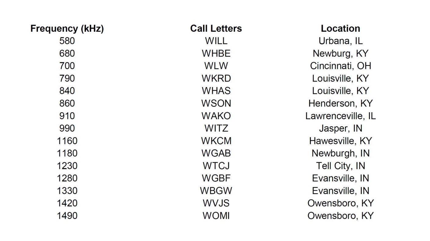
My in-home Part 15 AM transmitter is not included in the list above.
If the noise level had not been so high, I probably would have received more stations. However, receiving this many is unusual for my location, since we live in a very low-lying area. And most of my radios will not receive half of the stations listed above in the daytime.
About that power transformer…
I had previously mentioned how disappointed I was with the paint job I had applied to the bells and shield of the Philco 90’s power transformer. Every time I touched the chassis to move it, and placed one hand on the power transformer, I was reminded that no, the awful Rustoleum paint I had used had never fully dried.
So, on a particularly sunny and warm day, I set up my old folding table outdoors, and took out a can of acetone (my go-to general use fast stripper), a piece of 0000 steel wool, and a pair of rubber gloves.
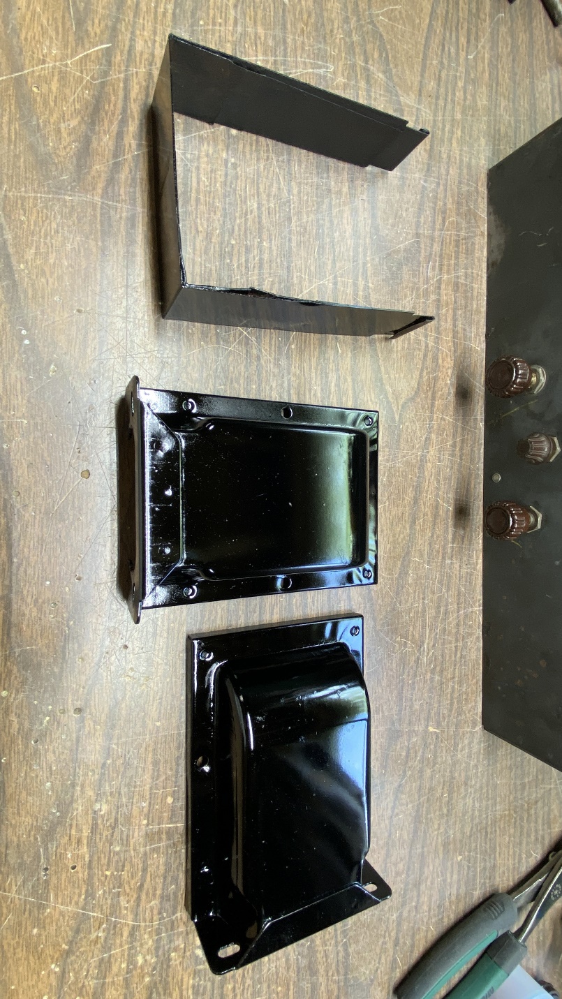
I removed the bells and shield from the power transformer for the second time, and took the parts outside to the folding table.
Fortunately, the Rustoleum came off the metal parts quite easily. As a bonus, the acetone also removed what was left of the original 1931 black lacquer, leaving bare metal pieces.
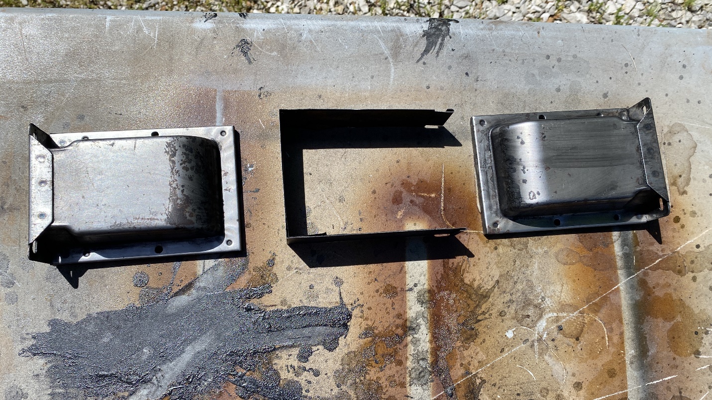
Power transformer end bells and center shield after stripping with acetone.
I let them dry in the sun for a while, and then lightly sanded them with 400 grit sandpaper to remove the few remaining spots of paint.
This time, I grabbed my can of Mohawk black lacquer, along with a can of clear gloss lacquer. I was not about to make the same mistake twice!
After mere minutes, this was the result…
The power transformer cover pieces, now painted with Mohawk black lacquer and coated with clear lacquer.
I brought the parts, still laying on the box I had placed them on to do the painting, into the house to fully dry overnight (even though lacquer normally dries to the touch in minutes, not hours).
The next day, I reassembled the power transformer.
Here is how the 90 chassis looks now:
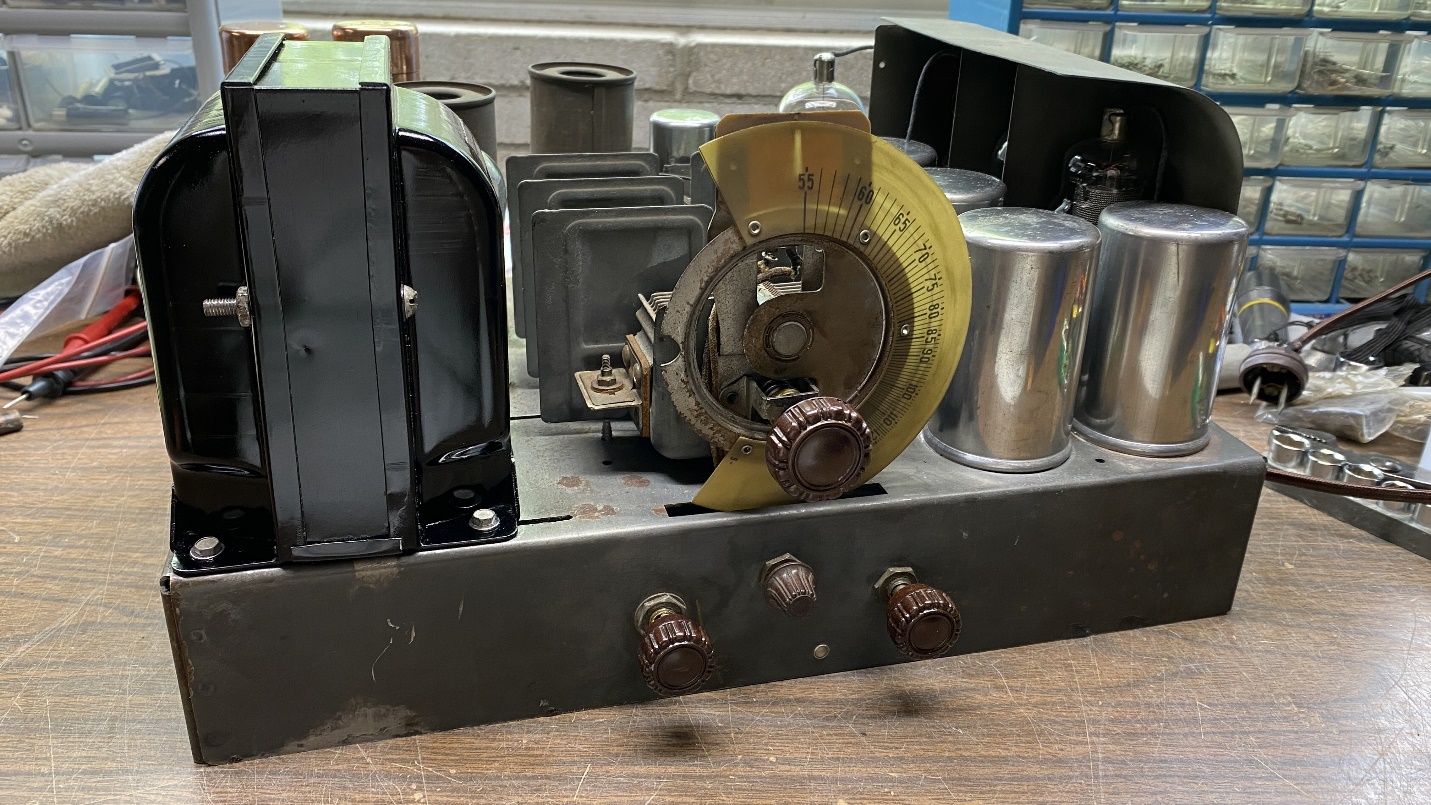
The finished Philco 90 chassis.
And the best thing – the paint was now dry, as it should have been.
I should also mention that the overheating the power transformer had obviously experienced at one time (evidenced by the black waxy substance which had been covering part of the chassis before I cleaned it) did not seem to harm the transformer. It runs fine, does not run hot or show any other evidence of imminent failure. Fortunately, Philco power transformers used in their 1928 – 1938 models seem to have been built very well and can withstand all but the most severe of overloads.
That, my friends, concludes the electronic restoration of this Philco 90 chassis. My next job is to come up with a speaker for it. I have a couple spare model 20 speakers, one of which would require a new cone. Both would require a different audio output transformer to match the single 47 tube to the voice coil. I’ll be looking for a solution in order to fully complete the radio. But in the meantime, let us bring this series to a close. I hope you have enjoyed reading along.