A recent thread in the Philco Phorum prompted me to start thinking about this subject. I can think of two different adaptors mentioned in Philco service literature covering various 1940 Philco radio models.
One in particular, which was the subject of the Philco Phorum thread mentioned above, was used for RF and IF alignment. The other was used for alignment of wireless remote control, also known as “Mystery Control.”
It struck me that this information needed to be documented. As far as I know, no documentation exists for the actual Philco radio aligning adaptor or the wireless remote control aligning adaptor. This article is intended to provide that documentation thanks to some reverse engineering.
In this article, I will describe how you may construct your own adaptors if you wish to have your own 1940 Philco “Radio Manufacturers Service” test bench setup, just as Philco dealers would have had at that period in time.
1. The Aligning Adaptor
Philco’s special aligning adaptor, part number 45-2767, was essentially a “straight through” test adaptor with a loctal tube socket on top and a loctal base on the bottom. It was designed to plug in to 1940 Philco radio models where a certain tube was ordinarily plugged in, namely, the 1232 converter tube or the 7C6 2nd detector/AVC/1st audio tube. (If the radio in question did not use a 1232 or 7C6 tube, that is a different issue and we will get to that later.)
By “straight through,” I am referring to each pin in the base of the adaptor having a wire connecting to the corresponding contact in the socket on top. In other words, pin 1 of the base connected to pin 1 of the socket; pin 2 to pin 2, etc.
In addition, the adaptor had two wires, a light wire and a black wire, protruding from the side of the adaptor. The light wire was connected to pin 6 of the base and socket; the black wire to pin 7 of the base and socket. See the wiring diagram below.
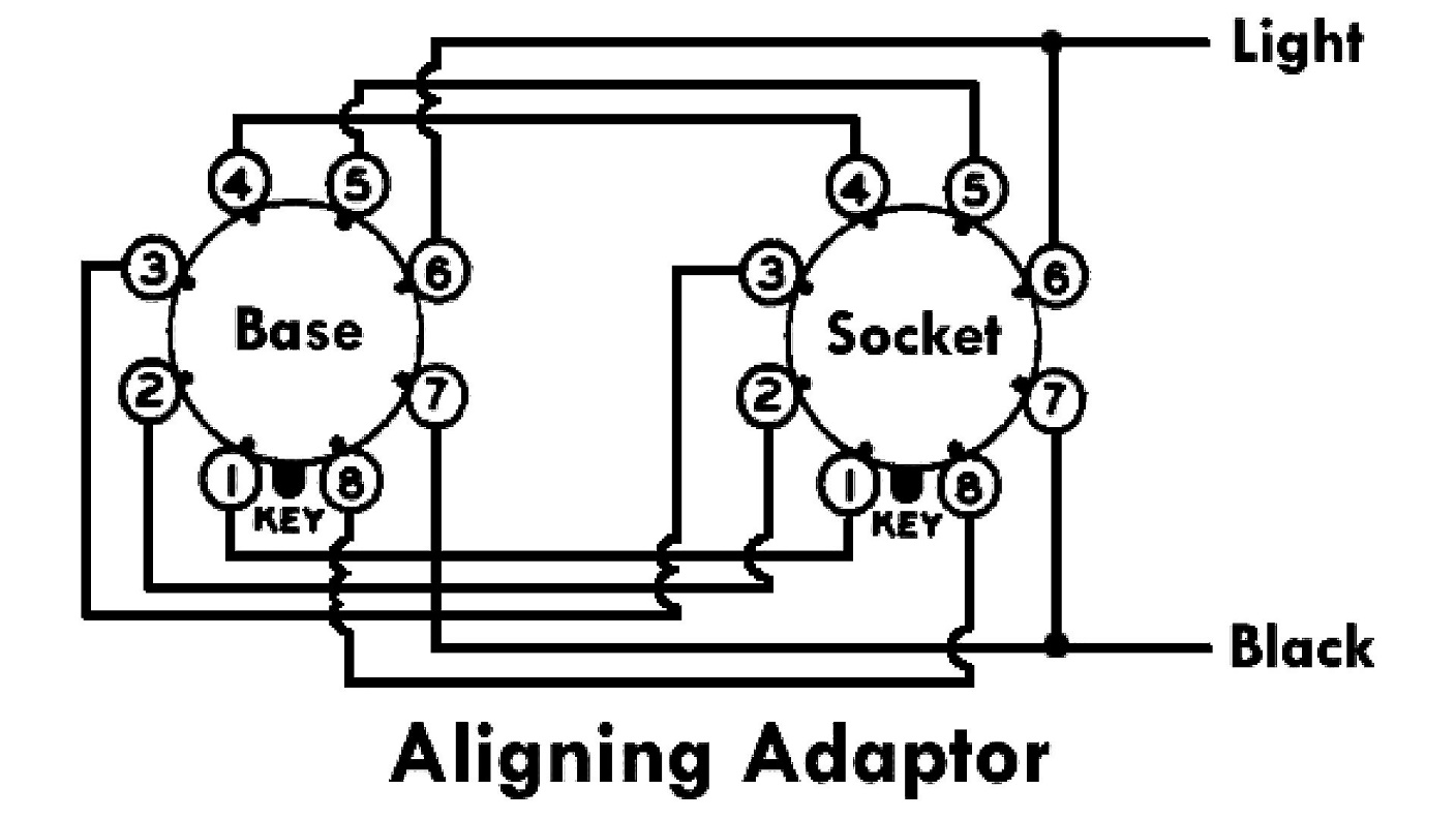
Schematic diagram of the Philco aligning adaptor.
How do I know these are the correct connections for the light and black test leads?
We can easily ascertain that this adaptor had a loctal base, and a loctal socket on top, with each pin of the base connected to the corresponding socket connection on top. That is to say, pin 1 of the base to pin 1 of the top socket, pin 2 to pin 2, pin 3 to pin 3, etc.
The real mystery lies in where those light and black wires would have connected in the adaptor.
To figure that out, careful study of a 1940 Philco radio schematic using a 1232 converter and 7C6 2nd detector-AVC-1st audio tube is called for. Let’s use a model 40-145 as an example.
Philco model 40-140 & 40-145 Service Bulletin
We know from the scant information given in the alignment instructions of this model, that the VTVM is intended to measure AVC voltage, which is a negative voltage.
Now we need to know which connections this aligning adaptor would have used which would have measurable AVC voltage in common so the adaptor could be used with two tubes with completely different pinouts.
Looking at the 40-140/40-145 schematic, we see that AVC voltage will be present at one of the 7C6 diode plates which is either pins 5 or 6. We also see that AVC voltage will be present on the 1232 control grid, pin 6. To measure AVC voltage with such an adaptor, a provision for a “low” or “ground” connection must also be provided.
On the 40-140/40-145 schematic, the two tube pins which have AVC voltage in common are – pin 6 for AVC high, pin 7 for AVC low or ground.
Therefore, a Philco “aligning adaptor” would have had a loctal base, a loctal socket on top, and wires connected from each pin of the base to the same corresponding pin on the top socket, plus – the “light” wire to pin 6 of the base & socket, and the “black” wire to pin 7 of the base & socket.
You may use the schematic above to construct your own aligning adaptor. An easy way to do this is to obtain a loctal test socket from someplace such as eBay. These test sockets come with tabs near the top which connect to the corresponding pins of the base/socket of the test socket. You may solder your “light” (I suggest you use red) and black wire leads to the tabs corresponding with pins 6 & 7, respectively.
In the service data for most 1940 Philco radio models, instructions for connecting an aligning meter are given as follows:
Audio Output Meter: If the Philco Models 027 and 028 audio output meters are used, they are connected to the speaker voice coil terminals or the plate and screen terminals of the (audio output) tube. (If the radio had a push-pull audio output circuit using two tubes, it was recommended to connect the output meter across the speaker voice coil or across plate and screen grid of one of the audio output tubes.) Adjust the meter to use the 0 to 10 volt A.C. scale.
To use the vacuum tube voltmeter as an aligning indicator, make the following connections:
Adjusting I.F. Circuit: Remove the 1232 R.F. tube from its socket and insert the aligning adaptor, then replace the tube in the adaptor. Connect the negative terminal of the vacuum tube voltmeter to the light colored wire which protrudes from the side of the adaptor. Attach the positive terminal of the vacuum tube voltmeter to the black wire of the adaptor.
Adjusting R.F. Circuit: To adjust the R.F. circuit, the aligning adaptor is inserted in the 7C6 second detector tube socket. The vacuum tube voltmeter remains connected to the adaptor as given in the paragraph above. With the voltmeter connected in this manner, a very sensitive indication of the A.V.C. voltage is obtained when the padders are adjusted.
What if the 1940 Philco radio model in question did not use a 1232 or 7C6 tube?
The service technician was then directed to connect the VTVM into the AVC circuit by connecting the negative or “low” lead of the VTVM to the AVC line, typically through a 2 megohm resistor. The positive or “high” lead of the VTVM was then connected to chassis ground. This was, in fact, the instructions given by Philco in its service data for 1941 and 1942 Philco radio models.
2. Wireless Remote Control Aligning Adapter
It is interesting that when Philco service data refers to the special adapter previously described, they spelled the word “adapter” as “adaptor”, yet they spelled the wireless remote control adapter as “adapter.”
But I digress.
The wireless remote control aligning adapter, part no. 45-2769, was designed to allow adjustment of the wireless remote control frequency.
Philco wireless remote control models used large remote control units which transmitted a form of pulse modulation in the longwave spectrum, typically between 355 and 395 kHz. The signals would “tell” the radio to turn the volume up or down, to select a particular preset AM station, or turn the set off. (The radio could not be turned on with the remote; you had to go over to the radio and turn it on manually.)
Philco began to offer wireless remote control in its two top of the line models in the 1939 model year – namely, models 39-55RX and 39-116RX. During the 1939 season, Philco called it “Mystery Control” – trying to keep the fact that the remote units were actually small transmitters a secret, referring to the control only as a “mysterious force.” Of course, the secret soon became widely known, and Philco referred to these models more properly as “Wireless Remote Control” beginning with its 1940 selling season.
Each wireless remote control Philco model was set up so it would use one of five different transmitting frequencies in the 1939 season: 355, 367, 375, 383, or 395 kHz. This was done in an attempt to prevent one person’s remote from accidentally controlling a neighbor’s wireless remote control radio. However, these radios were quite expensive in their day, and it was unlikely that two neighboring households would have one of these radios, even if the people lived in adjoining apartments. And if they did, the range of the remotes was a very short distance so the chances of a transmitter in one apartment controlling a wireless remote control Philco in an adjacent apartment was slim.
At times, it became necessary to align not only the radio, but the wireless remote transmitter and receiver. Philco service date for the 39-55 and 39-116 instructed the service tech to watch the 2A4G thyratron tube while the wireless remote circuits were adjusted, adjusting the padders for maximum brilliance of the 2A4G’s blue glow.
This soon proved to be insufficient, and Philco came up with a better solution in the second half of 1939 for its new 1940 models. That “better solution” was the 45-2769 wireless remote control aligning adapter.
The adapter was designed to be plugged into the Philco radio under test, in place of its 2A4G thyratron tube. It had two wires, a red wire and a black wire, protruding from it. A vacuum tube voltmeter would be connected to these wires. This was a much better solution, as the VTVM could then be easily monitored for maximum output when the circuit’s various padders were being adjusted. The VTVM also allowed for far greater accuracy when aligning these remote circuits.
Like the 45-2767 aligning adaptor described in part 1 of this article, the 45-2769 wireless remote control aligning adaptor was developed to meet a certain need. Of course, neither have been available for many decades. So, the hobbyist of today is forced to come up with their own solution.
As with the other aligning adaptor, it was necessary to study the schematic of a Philco wireless remote control model to determine exactly to which 2A4G pins the VTVM would have been connected.
We know the 2A4G had to be removed, and this adapter installed in its place. So, a small octal base was needed, small enough to fit into the hole in the steel base which is the bottom part of the 2A4G tube shield. Unless your radio has been modified, this shield base is designed so only a “G” style tube will fit.
Looking over a 40-216 schematic, we can reasonably ascertain that the voltage applied to the grid of the 2A4G is what needed to be measured. This places one of the adapter’s wires at pin 5. This point is also the top of the secondary of a transformer in the wireless circuit. The other end of that transformer’s secondary winding is connected to one of the 2A4G’s filament pins through a 0.5 uF capacitor and a 0.1 uF capacitor, in series. Looking at a typical remote control Philco chassis, it may be determined that the end of the 0.1 uF capacitor connects to pin 2 of the 2A4G filament.
So now we know where the wires should be connected – red to pin 5, black to pin 2.
Armed with this information, we may now construct our own wireless remote aligning adapter using the schematic below.
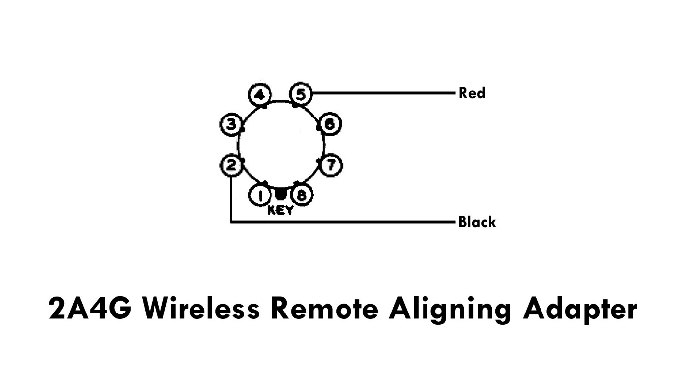
Using an old octal tube base, you may construct your own wireless remote aligning adaptor.
Once you have removed a small bakelite octal tube base from its glass envelope (the top portion of the tube which has a glass covering), remove all remaining tube lead wires from the pins. Now, cut a red wire and a black wire to a length of 6 to 8 inches each. Strip the red wire enough so that the bare lead protrudes from the end of pin 5 yet the wire sticking out on the other side is completely insulated. Solder this wire to the end of pin 5. Repeat this process for the black wire, only soldering it to pin 2.
For safety, I suggest you partially fill the inside of the tube base with hot glue, so there is no way to accidentally touch pin 3 from the inside of the tube base while the adapter is being used.
Now you have your own wireless remote aligning adapter, which may be used as if it were the original Philco adapter.
And that’s it. If you built the two adapters described above, you now have replicas of two small pieces of test equipment which Philco made available to its dealers around 1940 which you may now use to align your own Philco sets of the period.