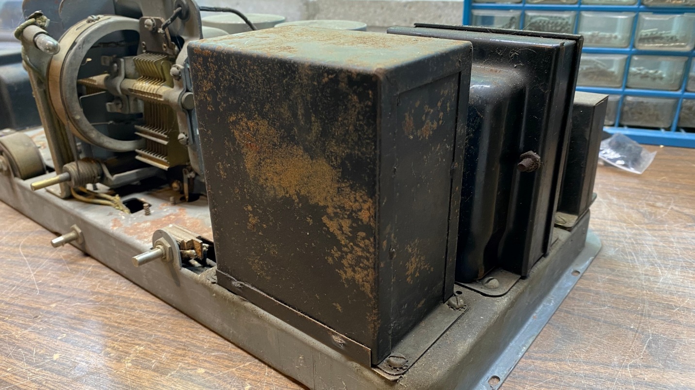
Another 1929 Philco, another filter condenser can.
I decided to begin my work on this Philco model 65 by restuffing and replacing the filter condenser block, part (20) on the schematic. This time, the job would be much easier than it was in my Philco 87 since I had an empty model 65 filter condenser block already on hand. So, it would simply be a matter of installing new components on the terminal board of the spare block, repainting its already-empty can, and installing the newly rebuilt block onto the chassis.
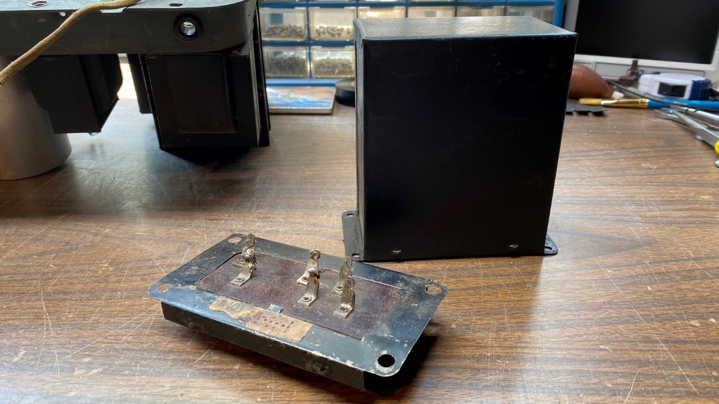
A lucky find in my parts stash – an empty Model 65 filter condenser can with base/terminal board.
Before proceeding, I needed a diagram showing what capacitors are used in this block and how they hook up on the terminal board. Fortunately, I had such a drawing, as seen below.
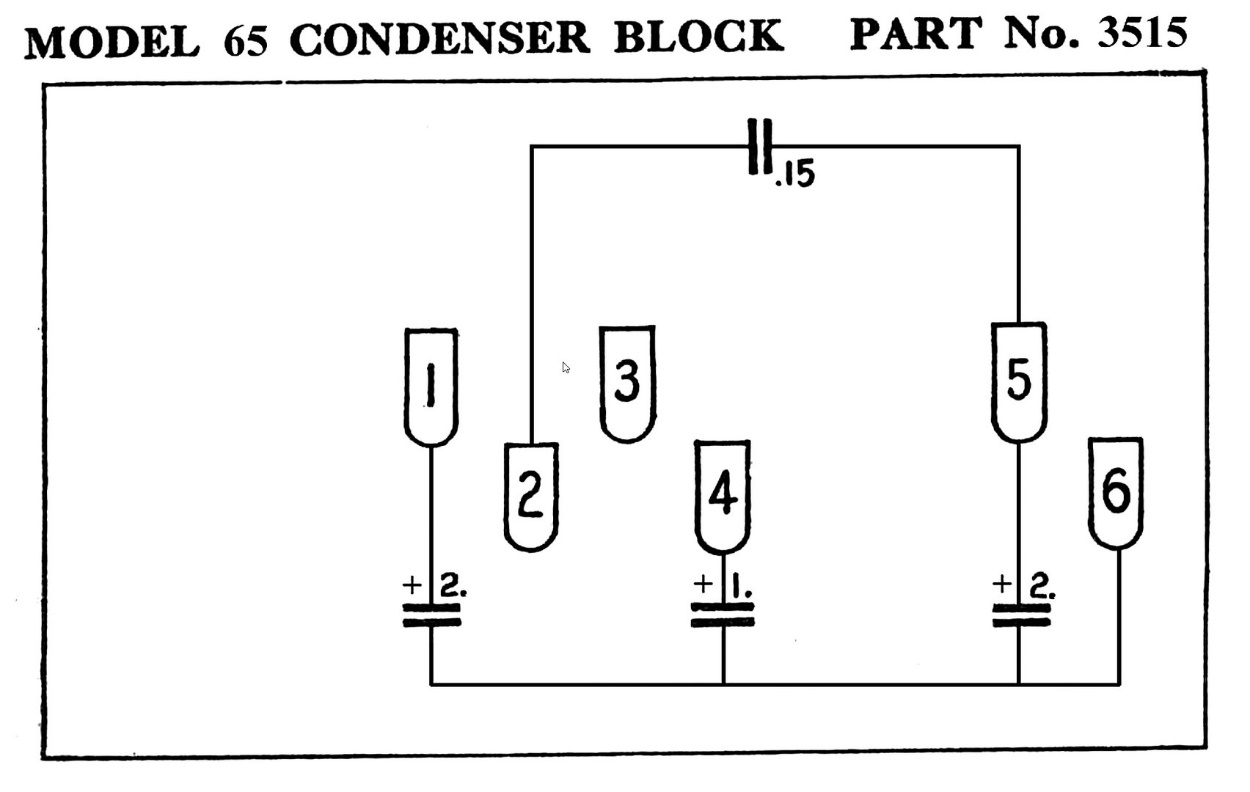
A diagram of the model 65’s filter condenser block, as it would be viewed from underneath where the terminals are located.
Now, as with the model 87, I also needed a diagram showing how the new capacitors should be connected above the chassis.
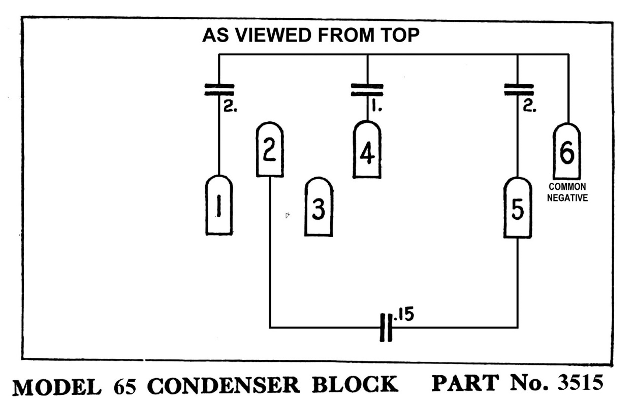
A revised diagram showing how the terminals look from above the terminal board (on the top side of the chassis).
After spending a little time with my favorite graphics program, I soon had the extra diagram I needed.
It was now time to remove the old filter condenser block from the chassis.
First, I had to disconnect all the wires underneath the chassis and remove resistor (22).
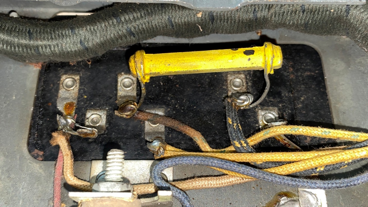
The original filter condenser block with the wires and one resistor still connected.
Then, I removed the four screws which held the block in place and pulled it free from the chassis.
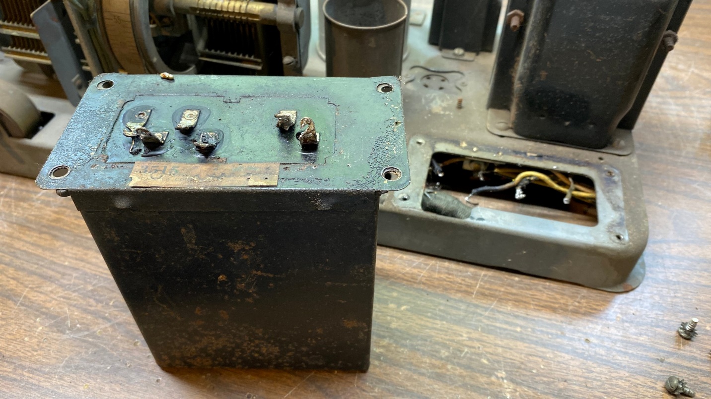
After removal of the original filter condenser block.
Let’s take a closer look at that label.
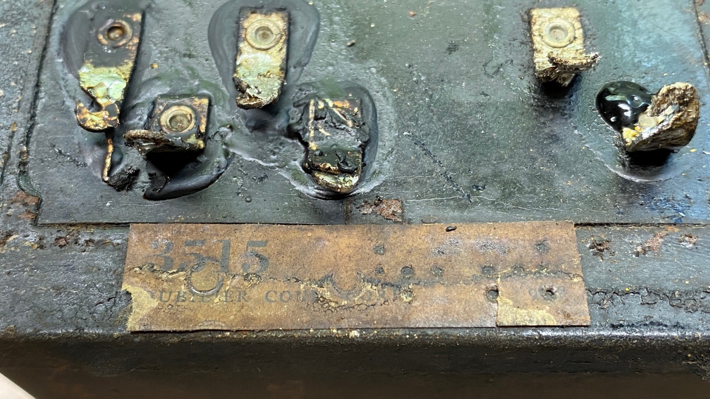
An original Dubilier label on the bottom of the original filter block.
The condenser can had been made by Dubilier Condenser Corporation, a forerunner of Cornell-Dubilier Electronics, which still manufacturers capacitors today.
The base of the spare can, including the terminal board. Someone had emptied out the can and added these components.
I put the old block out in the garage with the rest of my spare parts.
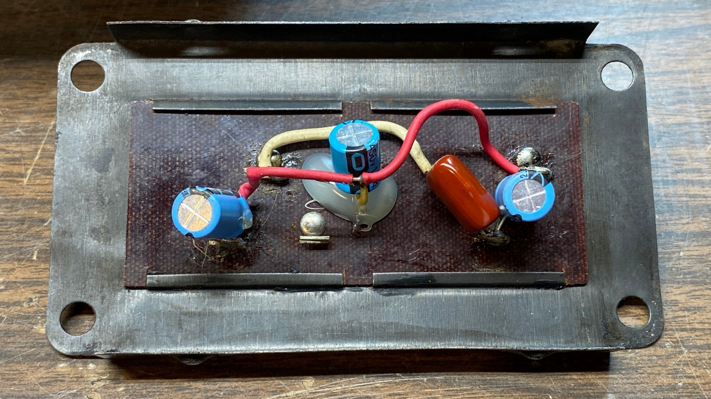
Now, taking the base of the empty can, I proceeded to remove the parts which someone had installed several years ago. Once the old parts had been removed, I installed all new parts, including 630 volt capacitors to replace the original paper capacitors.
The size of capacitors has certainly shrunk in 92 years, haven’t they?
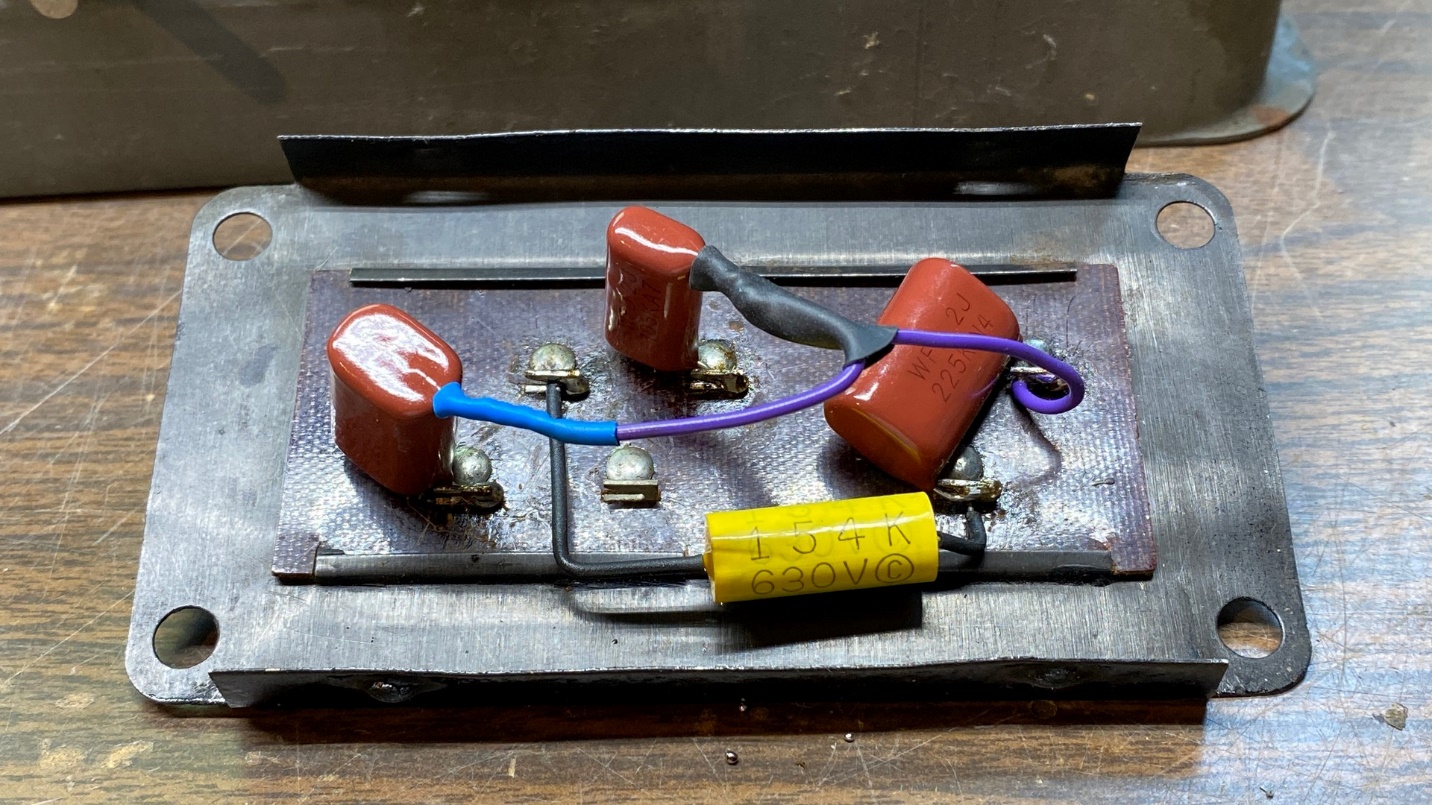
New capacitors added to the top of the terminal board.
Next, I placed the newly rebuilt base of the can onto the chassis, temporarily bolting it into place. After that was done, the chassis was turned upside down so I could reattach and resolder all the leads. The radio also received a new 5000 ohm, 1.5 watt resistor to replace the original 5000 ohm, 1 watt yellow resistor, part (22).
Here are how things look at this point.
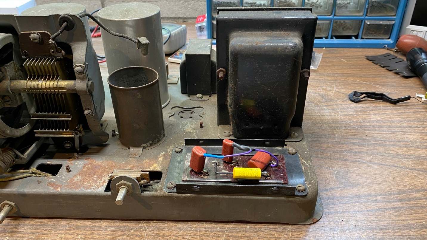
The rebuilt block base on the chassis.
And a look at the terminals underneath the chassis:
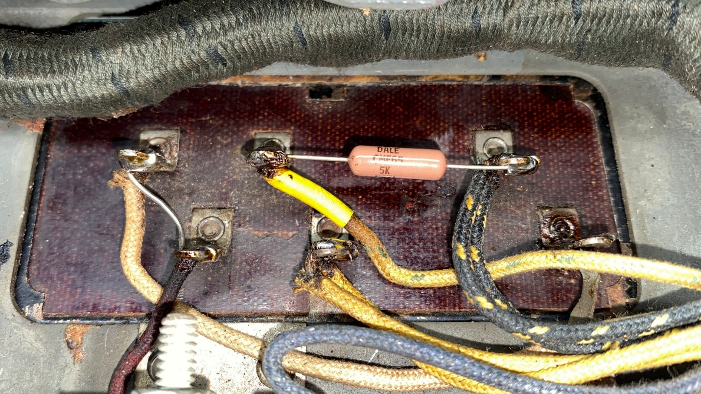
All wires have now been reattached and soldered in place under the chassis, and a new 5000 ohm resistor has also been installed.
I will install the metal can (cover) later, after I have worked on the set’s power transformer. That transformer, like the model 87’s power transformer, also has rubber-covered wires protruding from its base, and that hardened rubber insulation will have to be replaced. I will get into that job next time.