As you may recall, I wrote an introductory article about this FM-200 in this blog post. Even though I acquired this tuner in pieces from two different sources – and it is not yet complete as it still needs a bottom cover and the proper knobs – I still consider myself fortunate to have acquired it. The FM-200 was produced for less than a year by Fisher before becoming obsolete with the finalization of the FM Stereo standard by the FCC in April 1961.
The FM-200 is the best mono FM tuner Fisher had ever built. It included every possible bell and whistle Fisher could throw at it in late 1960. Advanced features such as separate 300 and 72 ohm FM antenna inputs, selectable at the front panel; muting; audio level control on the front panel; and automatic frequency control (AFC).
Fisher even went one better than just AFC – the new Microtune circuit was also included. This acted as an automatic AFC. If the AFC control was set to Microtune, when the user touched the tuning knob, Microtune was disabled and the user could tune in a station normally. When the tuning knob was released, Microtune would kick back in (via a relay in the tuner circuitry) and would hold the station in perfect tune.
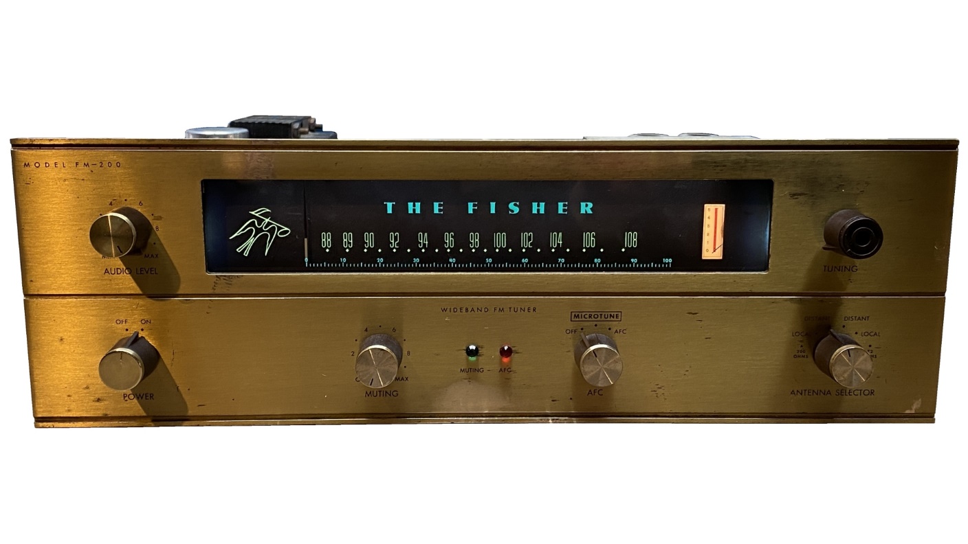
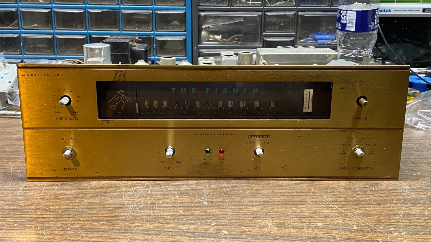
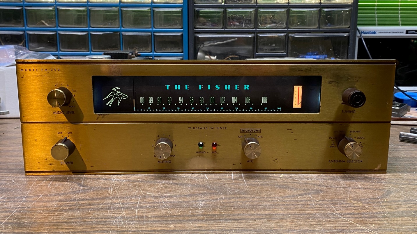
Once I received the dial glass and front panel to go with the barebones chassis, my FM-200 looked as you can see in the image above.
Now for an explanation about my entire “Christmas Radio” idea. Each year for the past decade or so, I have selected one radio to restore as a Christmas present to myself. And since I became interested in Fisher gear about six years ago, I have restored Fisher items as well as vintage radios over the years.
So now it was time to begin restoration work on this FM-200.
When I start working on an electronic project, be it a radio, tuner, or receiver, I do not typically begin at the same point in the circuit – instead, I merely pick a starting point and dive in.
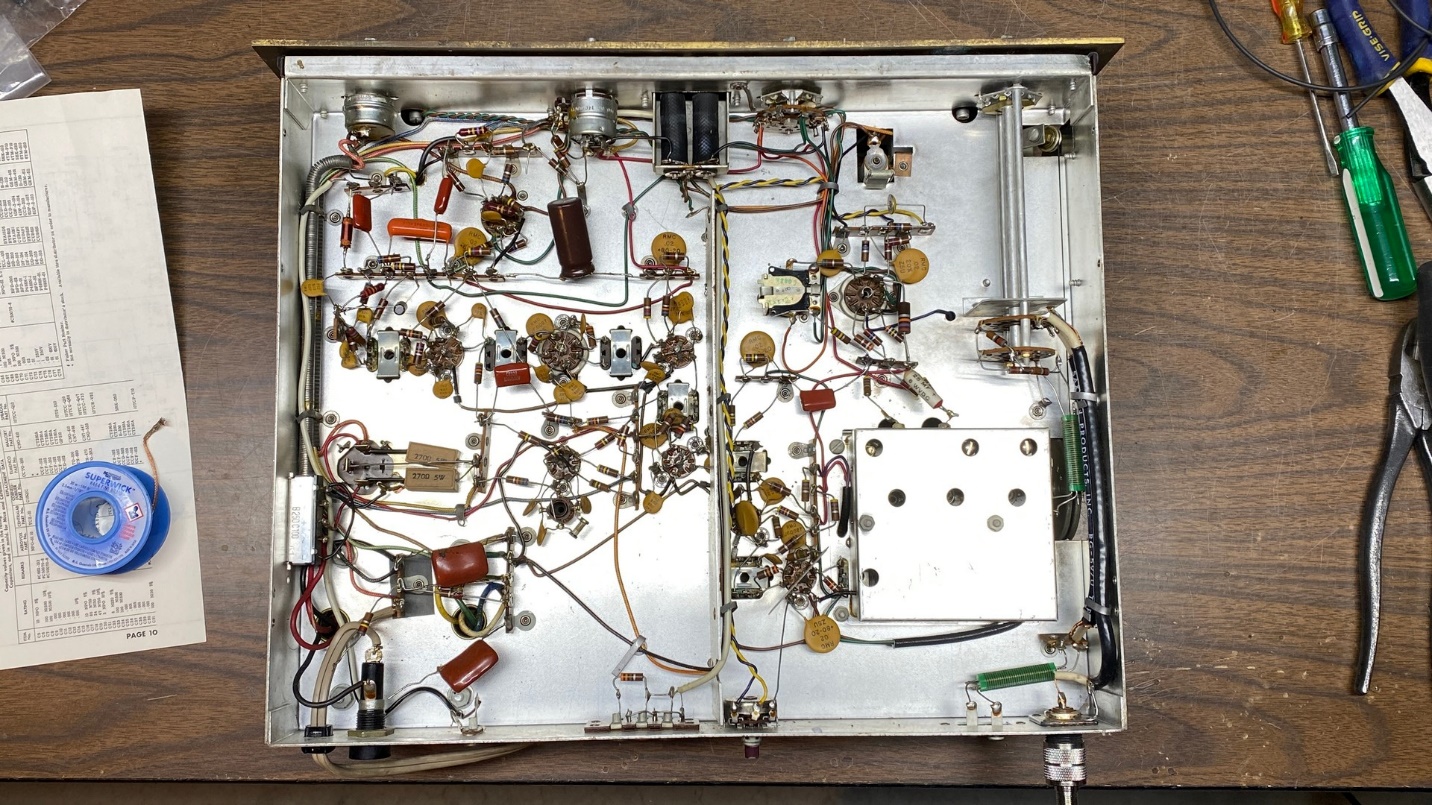
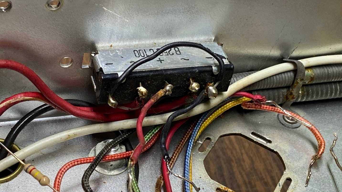
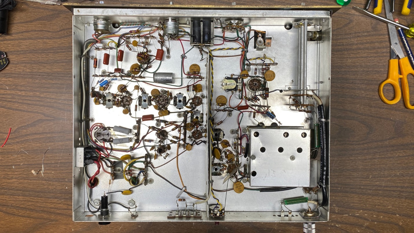
The photo above indicates that this FM-200 had been worked on by someone in the recent past. Whoever tried to work on it did not replace the selenium rectifier or the original multi-section electrolytic can, though. I will replace the selenium rectifier and rebuild the multi-section electrolytic can.
But first – let us address those poor substitutes for the original “death caps” – the AC line bypass capacitors.
Safety First
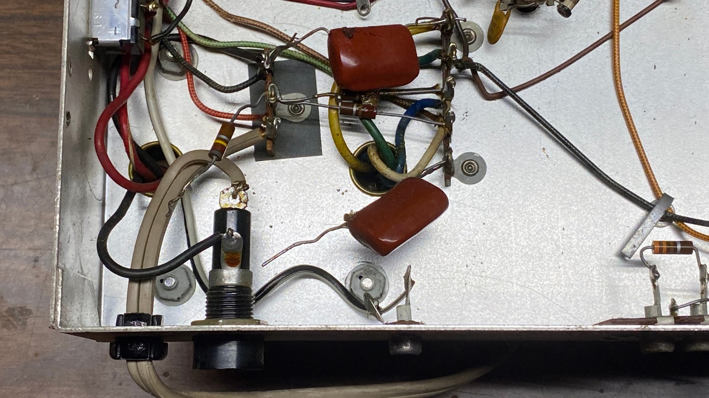
Someone had installed two mylar .01 uF, 1000 volt capacitors in place of the originals. This is not desirable from a safety standpoint. A capacitor which is connected from the AC line to ground needs to be a Y rated capacitor. Capacitors which are connected across the AC line are X rated capacitors (no, not that kind of X rated).
In normal use, the safety capacitors we can use in our old electronics carry an X1/Y2 rating and may be safely used for line-to-line or line-to-ground applications. In the FM-200, these capacitors are connected from each side of the AC line to chassis ground.
These safety capacitors are designed to fail open. This means that if they fail, they will go “open circuit” and not short. A capacitor which shorted out would be a major safety hazard. Standard capacitors such as the two someone put into this FM-200 could fail open or shorted. Not a good thing. You can see in the image below that I replaced these with two X1/Y2 safety capacitors.
The original fuseholder was missing its cap. I replaced the fuseholder with a new one, which had its cap. The cap is not illustrated below as I had not yet inserted a new 1 amp fuse.
A Baffling Omission
I decided to just go ahead and replace all of the previously replaced mylar capacitors.
I did not have the original Fisher factory service information for this tuner; instead, I had the Sams Photofact for this tuner. Because Howard W. Sams & Company still maintains copyright on all of their Photofacts, I am not able to share the entire schematic with you here.
However, I am going to take a couple liberties and show you a couple partial circuits to illustrate some important points.
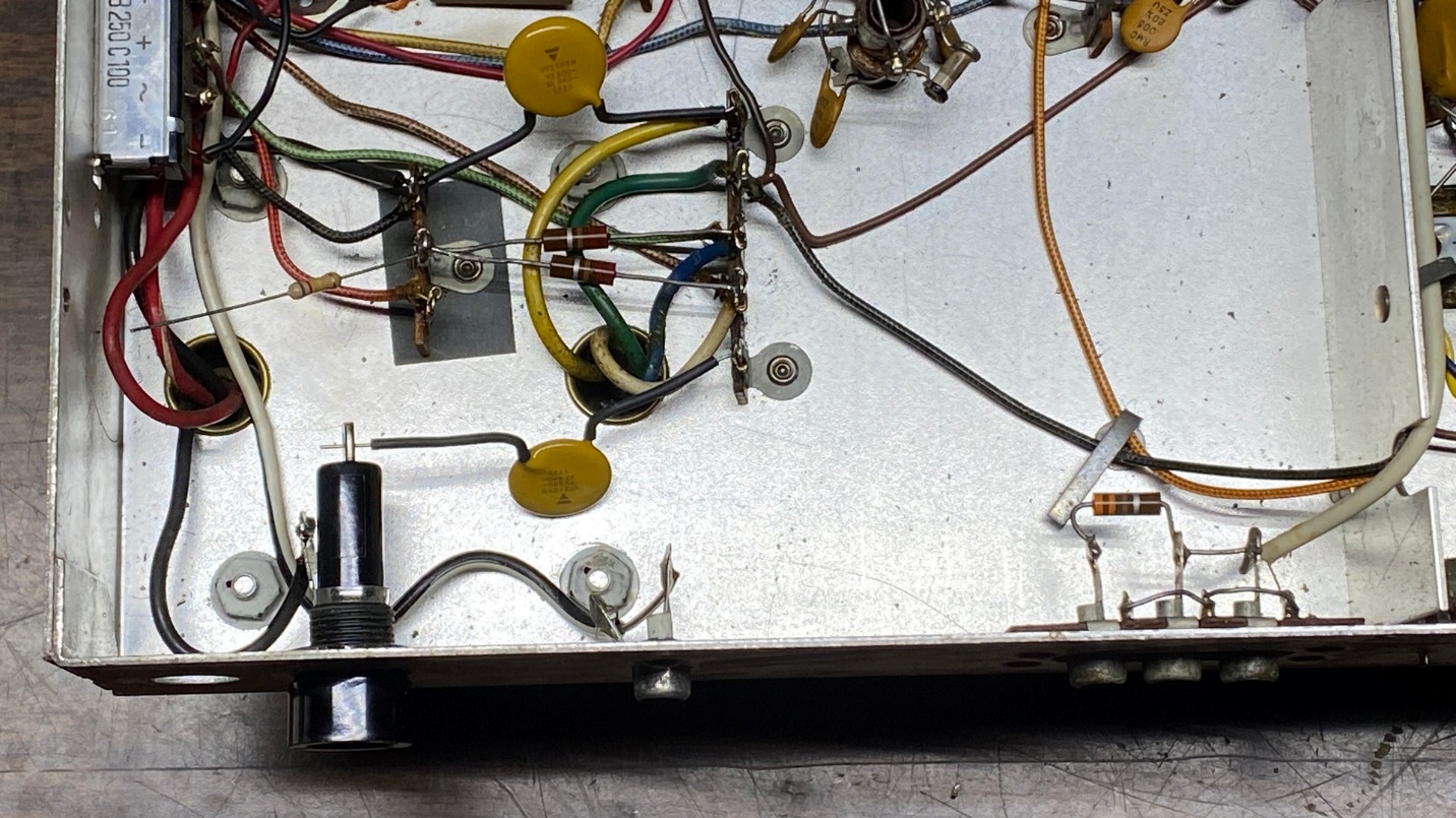
I noticed there was a cut off wire connected to pin 8 of the 12AX7 audio preamp tube. Another cut off wire was connected to the terminal strip where a shielded wire ran to the back of the chassis and the audio output jacks.
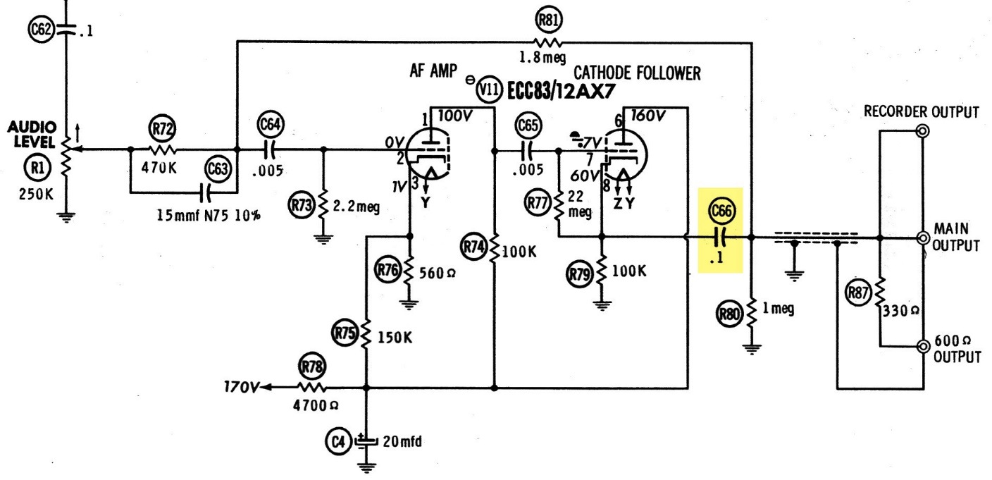
The cut off wires originally connected to C66 as highlighted in the partial schematic above, 0.1 uF. With no C66 in place, no audio would reach the audio output jacks. Could this be why someone gave up on this tuner – they forgot to install a replacement for C66 and then, of course, the tuner outputted no sound?
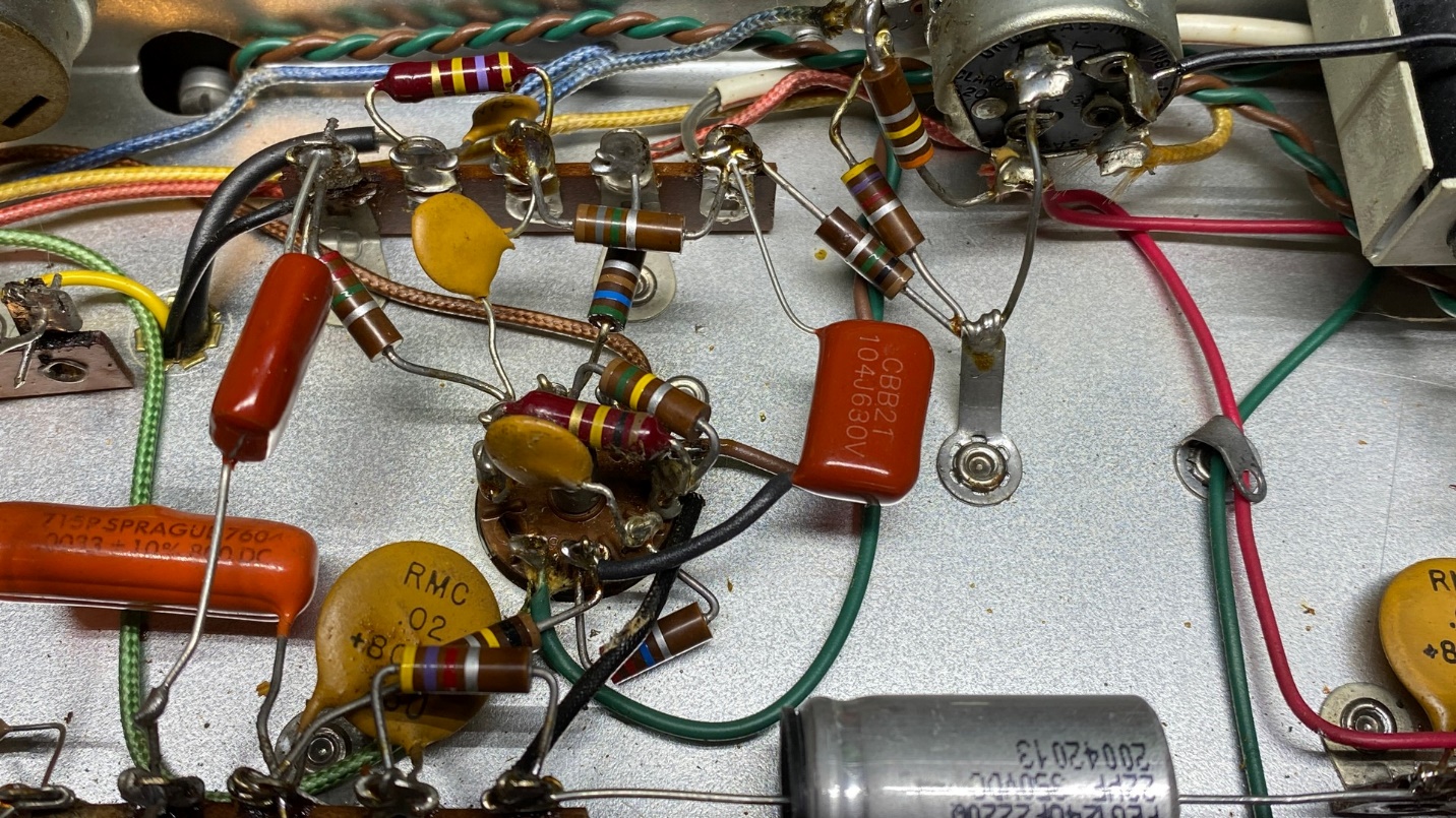
I do not know the answer to that, but I made sure to install a new C66 as you can see below.
Working on the Power Supply
Once all the mylar capacitors were replaced (as well as the two standalone electrolytic capacitors), it was time to turn my attention to the tuner’s power supply.
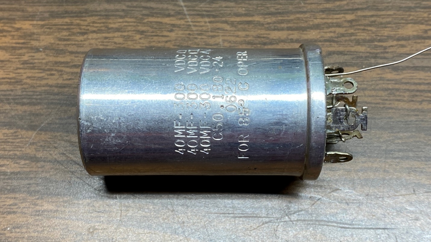
I had mentioned previously that the tuner still had its original three section electrolytic can capacitor. I removed the connections to this capacitor, and then removed the capacitor can itself.
Next, I removed the original selenium rectifier. Selenium rectifiers are often found in Fisher equipment. They were made by Siemens in Germany. Nearly 60 years on, they have usually gone bad or are on the brink of doing so, and these should always be replaced with silicon rectifiers.
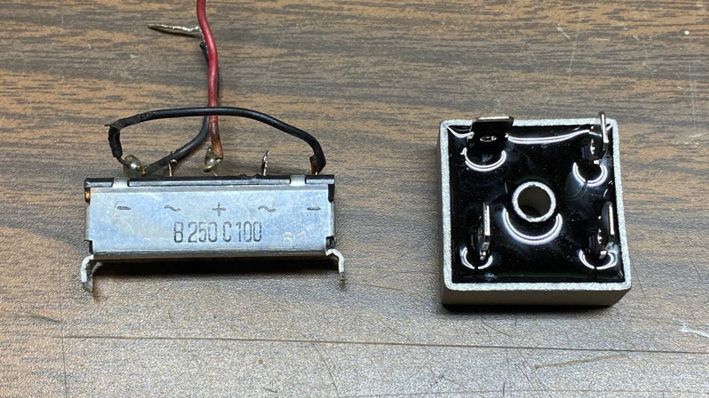
In the picture below, you will see the original Siemens selenium rectifier next to its replacement, a silicon bridge rectifier.
The silicon bridge is rated at 1000 PIV, 10 amps. Yes, this is a far greater current rating than is needed for this tuner. However, the stud terminals are quite convenient for connecting wires, so I generally use these anyway if there is room under the chassis.
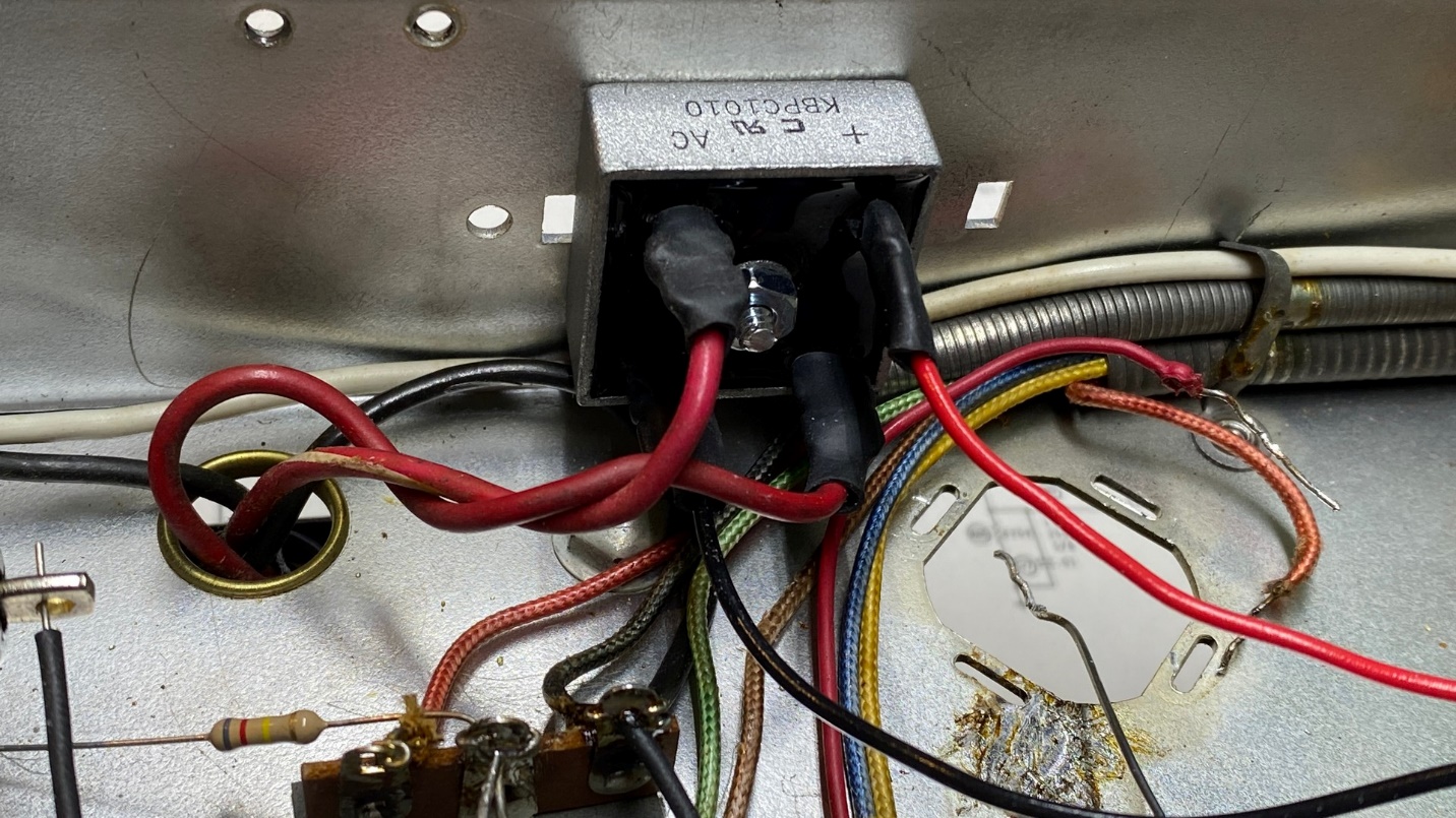
Once the new silicon bridge rectifier was installed in place of the selenium rectifier, things looked like this:
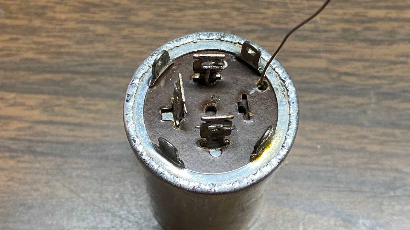
Now it was time to address the three-section electrolytic capacitor can.
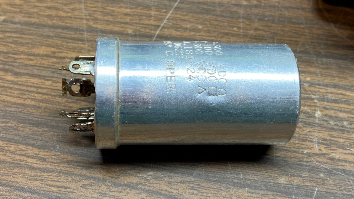
I have developed a method of rebuilding these twist-lock cans. I carefully cut away the bottom lip of aluminum with a box cutter knife.
Safety First! I always cut the “lip” so that the knife is going away from me so if I slip, no harm will be done. The aluminum is surprisingly easy to cut. I cut the lip as if I were using a saw, and it generally never slips. You must be careful if you do this. Use common sense. Cut away from you, never towards you.
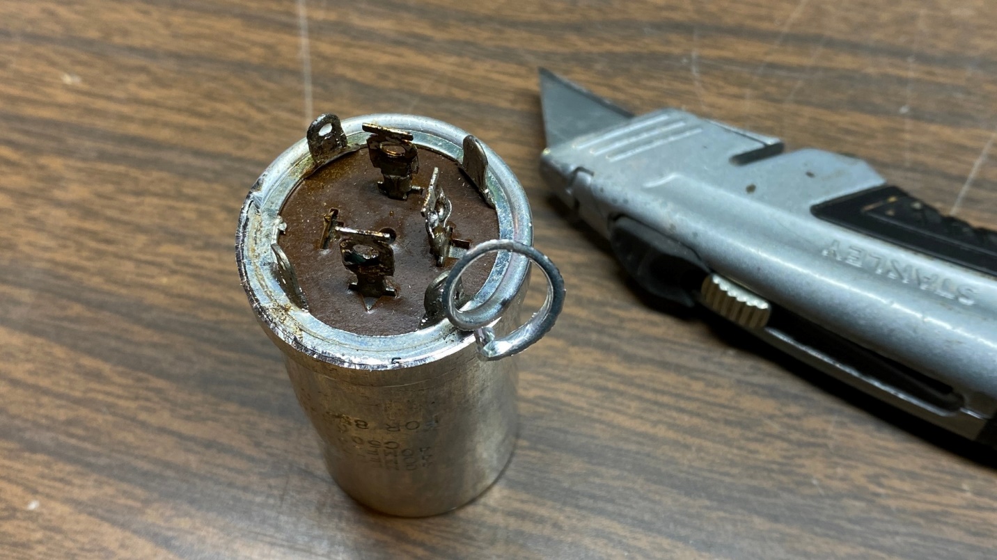
Once I finished cutting the “lip” away, I was able to pull the unit apart. It is a good idea to clean out the inside of the can as best as you can. Lacquer thinner works well to remove any tar residue.
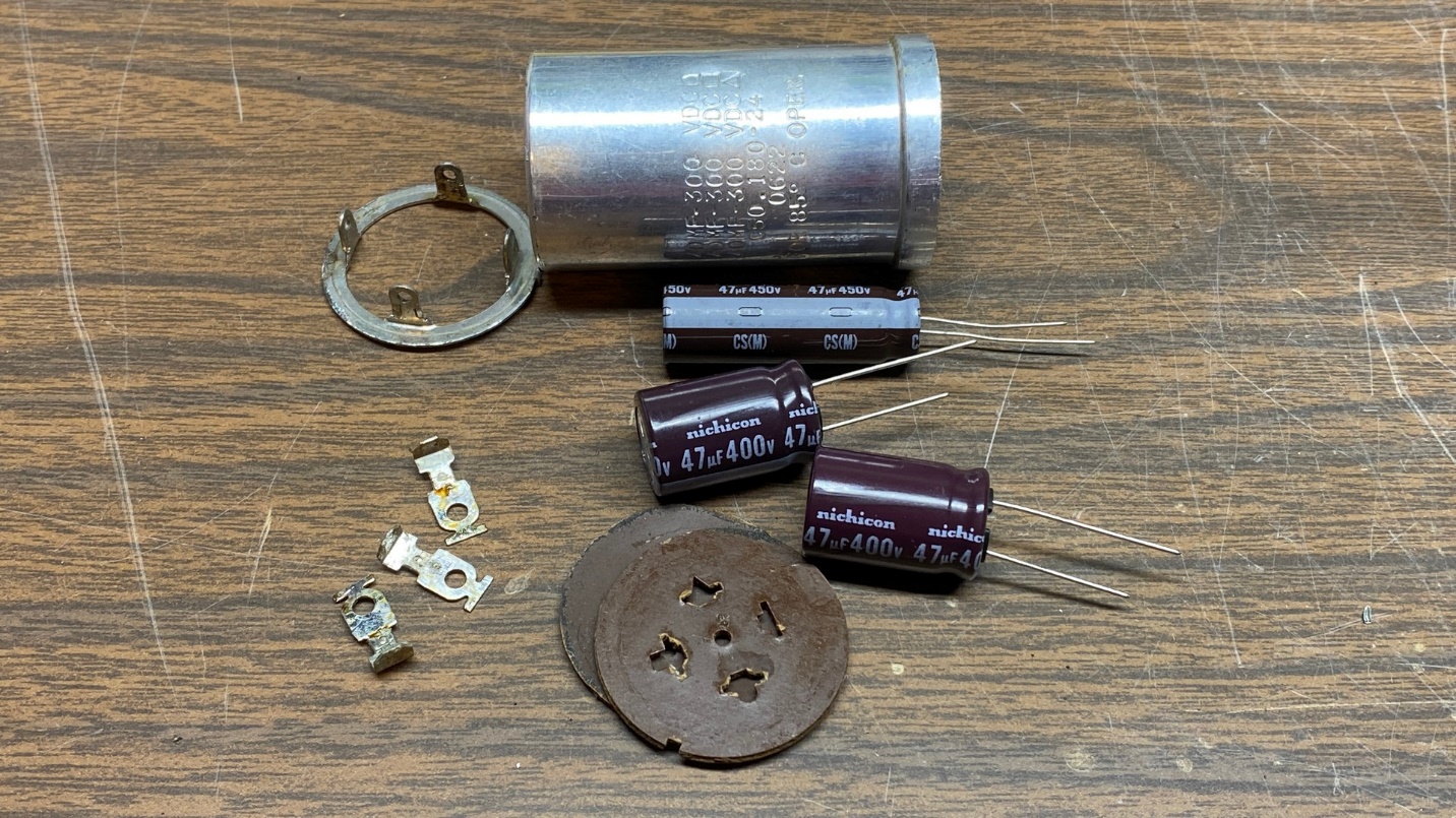
As luck would have it, the new 47 uF Nichicon electrolytic capacitors were too large for this application. I will have to pay more attention the next time I order these. Fortunately, I happened to have two slimmer Nichicon 47 uF capacitors and I used these, along with one of the larger 47 uF units, so they all fit – barely – inside the can.
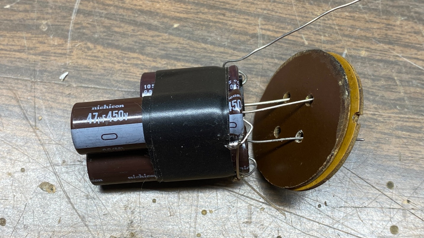
I drilled an extra hole in the phenolic for the ground lead and put everything back together, and then inserted the new capacitors into the old can.
After adding the metal base with the twist-lock tabs, I carefully pressed or “rolled” the aluminum over the edges, creating a new “lip” as seen below.
Now you may be wondering – How did I have enough aluminum to be able to roll a new “lip”?
Simple, really. In between the two pieces of phenolic is a thick layer of rubber, I simply eliminate the rubber piece and when I reassemble the can, the elimination of the rubber layer leaves enough material to roll a new “lip”.
And now the electrolytic can capacitor will appear as original when it is reinstalled on top of the tuner chassis.
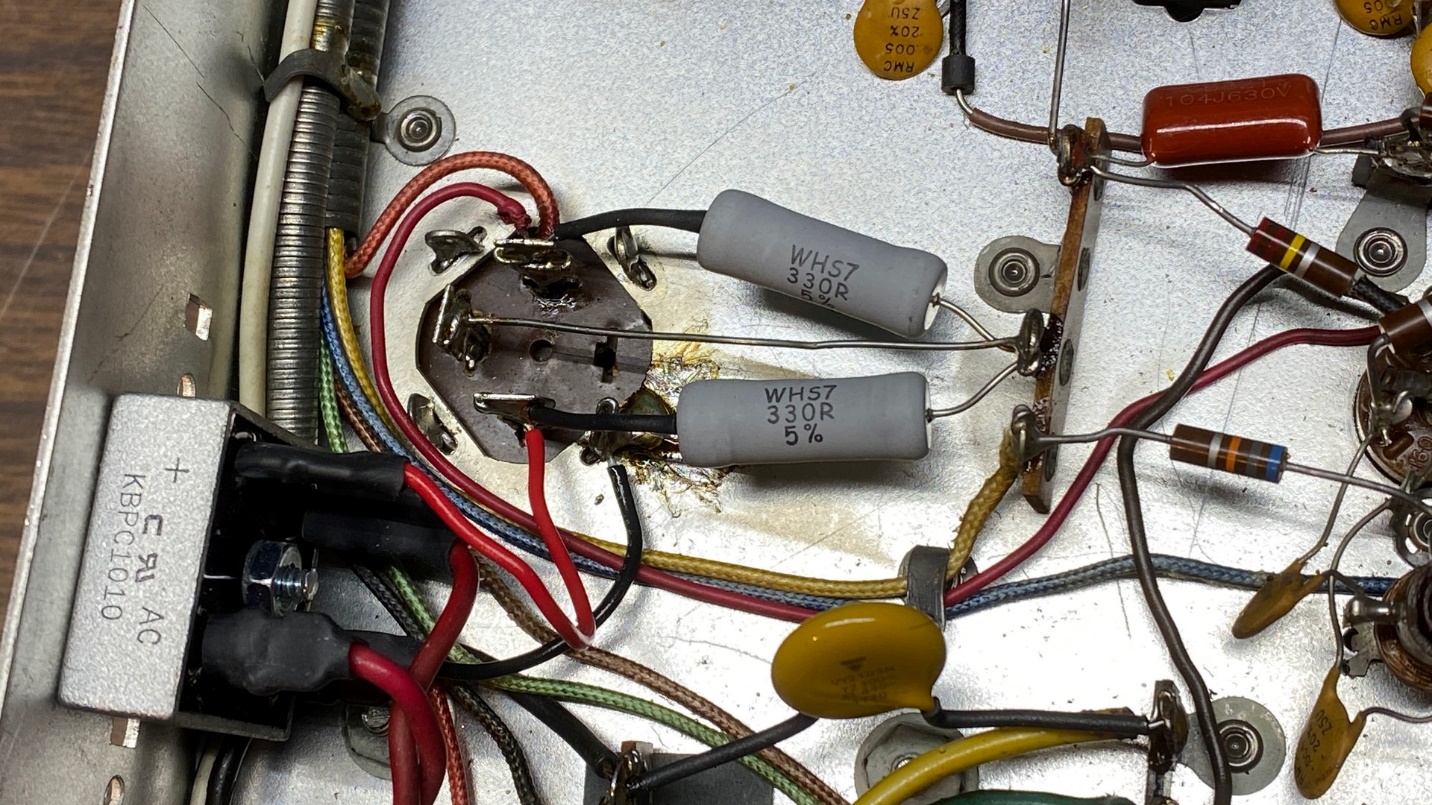
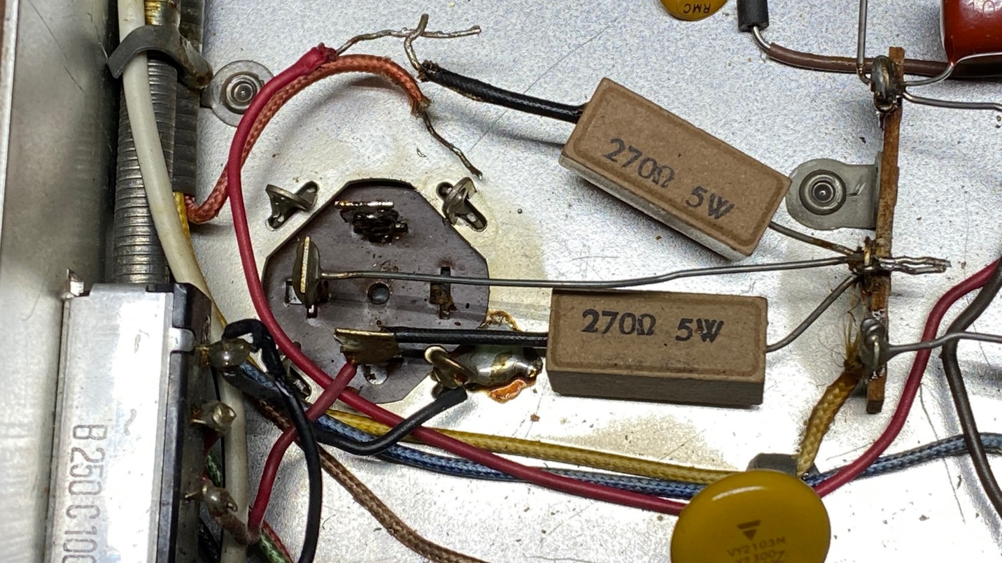
After reinstalling the rebuilt electrolytic can, I reattached the wires. I also installed two new 330 ohm, 7 watt resistors in place of the original 270 ohm, 5 watt resistors.
Why 330 ohms instead of 270 ohms? A silicon bridge rectifier is more efficient than the original selenium and has a much lower voltage drop. If resistance is not added to the DC output, the B+ voltage will be too high.
The conventional way to address this issue is to add a 100 ohm resistor in series with the bridge rectifier output and B+. In this case, I found it more convenient to add the resistance to the two power resistors instead, which gives the same effect. Well, since I used 330 ohm resistors, this adds 120 ohms in series with B+ instead of 100 ohms, close enough.
An Error in the Photofact
When I replaced the 8 uF electrolytic in the ratio detector circuit, I was confused by the placement of this 8 uF unit on the Photofact schematic. See the original partial schematic below.
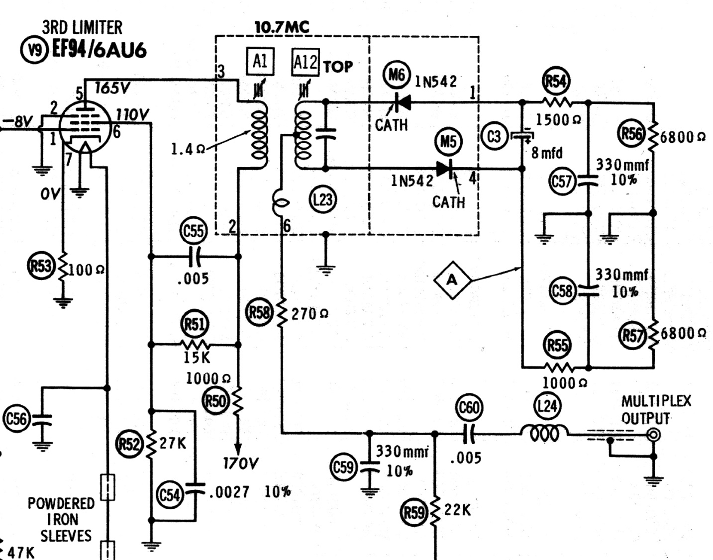
As it turns out, C3 is not placed properly in the original Photofact schematic. I have corrected its placement in the partial schematic below.
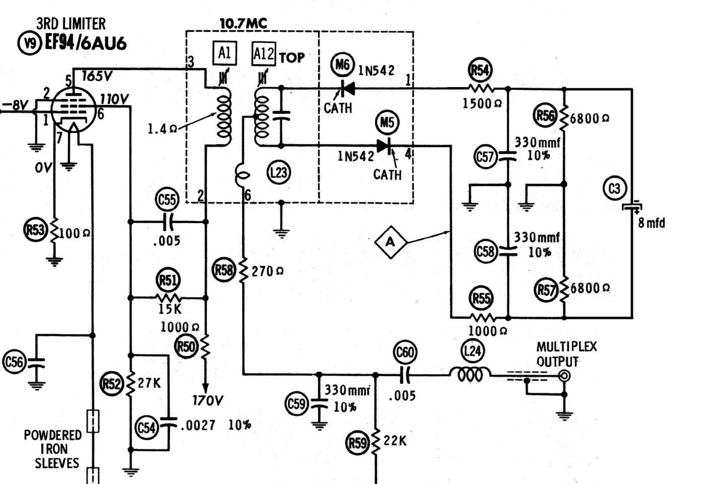
The above matches the connection of C3 as it existed under the chassis of my FM-200.
I should make one more observation about this circuit. Following my conversations with an acknowledged Fisher expert a month or so ago, I eliminated C60 (.005 uF) and replaced it with a solid wire. I will be using a solid state multiplex decoder with this FM-200 later on, so replacing C60 with a wire as the Fisher expert recommended is my way of preparing this tuner for use with the solid state multiplex decoder.
Once all of the paper and electrolytic capacitors, bridge rectifier, and fuseholder was replaced, the underside of the chassis looked as shown below.
Final Touches
When I received the FM-200 barebones chassis, I noticed that someone had soldered tiny “grain of wheat” bulbs to the festoon lamp connections on either side of the dial. These would not provide much illumination to the dial glass!
I removed the caps from two bright white LED fuse lamps, soldered wires to their ends, and hard wired them on either side of the FM-200’s dial glass.
As received, the FM-200 barebones chassis had a very short power cord. Perhaps it had been custom installed into a cabinet or wall originally. I wanted something longer to easily reach outlets, so I installed a new AC cord, 7 feet in length.
I carefully polished the brass front panel. Much to my surprise, the marks above and below the left side of the dial opening mostly came off. The front panel is still flawed, but I can live with that simply because I know the chances of finding a better front panel are somewhere between slim and none, since the FM-200 was produced for less than a year and likely in low quantities.
I still had no knobs, so for the time being, I am using knobs from early Fisher transistor equipment. They will serve the purpose.
Now – the big question – Will it work?
Success!
I connected a long wire to the 300 ohm antenna terminal which did not connect to ground. I connected the audio output to my workbench Lepai LP-2020TI amplifier (which is a great bargain and is an excellent low power amplifier).
I plugged in the tuner and turned it on.
After a 15-20 second warmup, the familiar FM hiss could be heard. Soon I was tuning in FM stations. Lots of them. This FM-200 was picking up stations with ease. I can only imagine how well it would do with an outdoor FM antenna.
If you want more proof, you can click here to see a video on my YouTube channel.
I found that Microtune worked just as it should. When I set the AFC knob in the Microtune position, I could purposely mistune a station and when I let go of the tuning knob, Microtune would bring the station in perfectly.
I love how that dial “pops” with those bright white LEDs. They make the white numbers and the Fisher “bird” logo look bright white, while the turquoise THE FISHER lettering and the log scale look just great.
The FM-200 does have two issues. One – all FM stations are shifted to the left of the dial a bit much. 95.5 is coming in at 94.7 on the dial, while 104.7 comes in with the dial set at approximately 103.9. An RF alignment will take care of that. Two – the Muting circuit is not working. I will have to look into that.
And I still need to find a bottom cover as well as the proper knobs. But otherwise, this was a nice project which came together quickly, and it is a great tuner overall.
Yes, I can mark the FM-200 off my “want list”. Merry Christmas to me!