Time for a good cleaning.
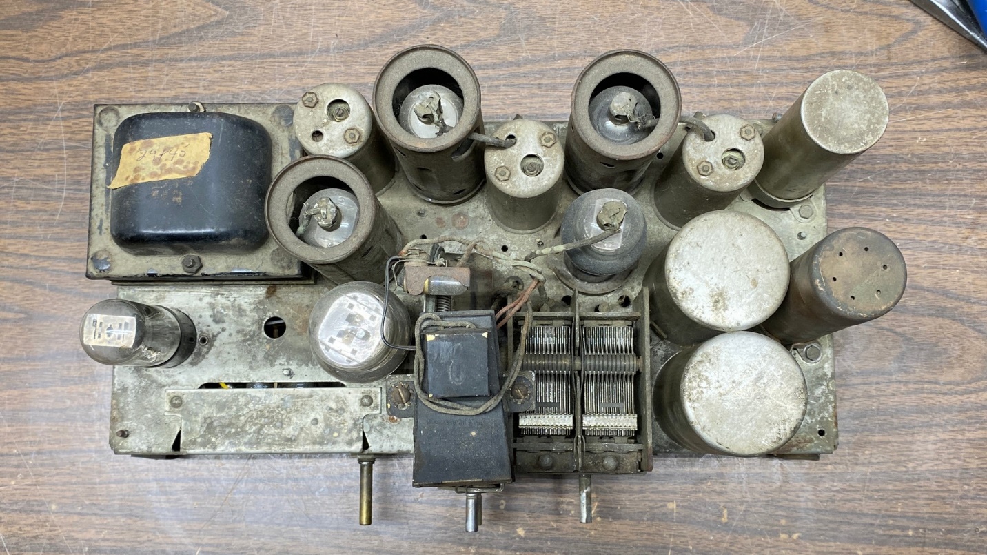
I took a good look at the top side of the Model 29 chassis. It was very dirty, as you can see in the “before” photo above. I therefore made the crazy decision to clean the chassis. With all the obstacles on top of this chassis (tube shield bases, three IF cans, two RF coil shields, power transformer and tuning condenser), this would be no easy job. But I was going to do the best that I could.
I realized it would be a little easier if I removed the two RF coil shields. These shields were connected together, but were mounted to the chassis in an odd manner. The shields have three chassis mounting tabs. One is held in place with a short self-tapping bolt. The other tabs were riveted to the chassis.
I removed the bolt, drilled out the two rivets, and removed the coil shields.
Then, over the next few days, I rubbed down the chassis to the best of my ability with waterless hand cleaner. Once I completely wiped off the chassis, I went over it again with Mothers Mag & Aluminum Polish, also using Mothers on the IF can shields.
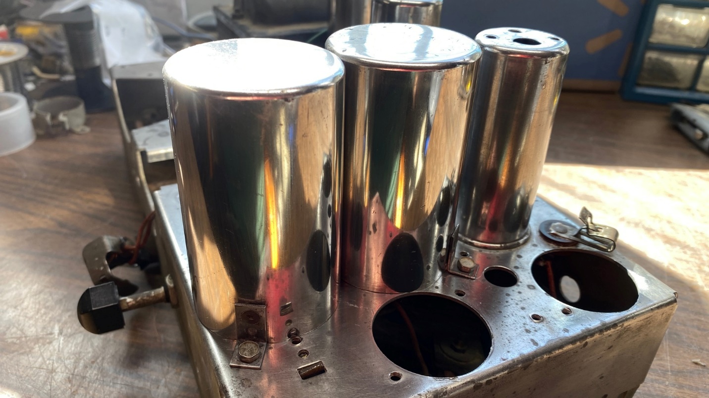
The results may be seen below.
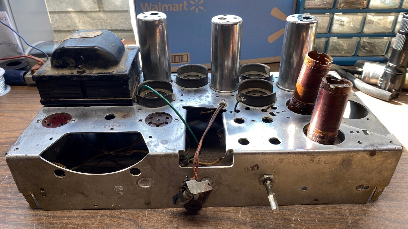
The cleaned and polished Philco 29 chassis.
Since I had the IF transformers out of the chassis, it was easy to polish the IF can shields. I should say something about those shields at this point. Each of these are held in place by a “C” clip on top of the chassis, at the bottom of each can. I caution you to not attempt to remove these. The only way to get those “C” clips off is to pull them up along the cans, finally pulling them free from the top. This will permanently scar and damage the cans. Been there, done that, was not about to try it again this time.
The cleaned and polished chassis, as viewed from the top.
Using some more Mothers Mag & Aluminum Polish, I carefully polished the dual coil shields. Once this was done, I reinstalled them on top of the chassis. In order to do this, I used three short self-tapping bolts instead of any rivets.
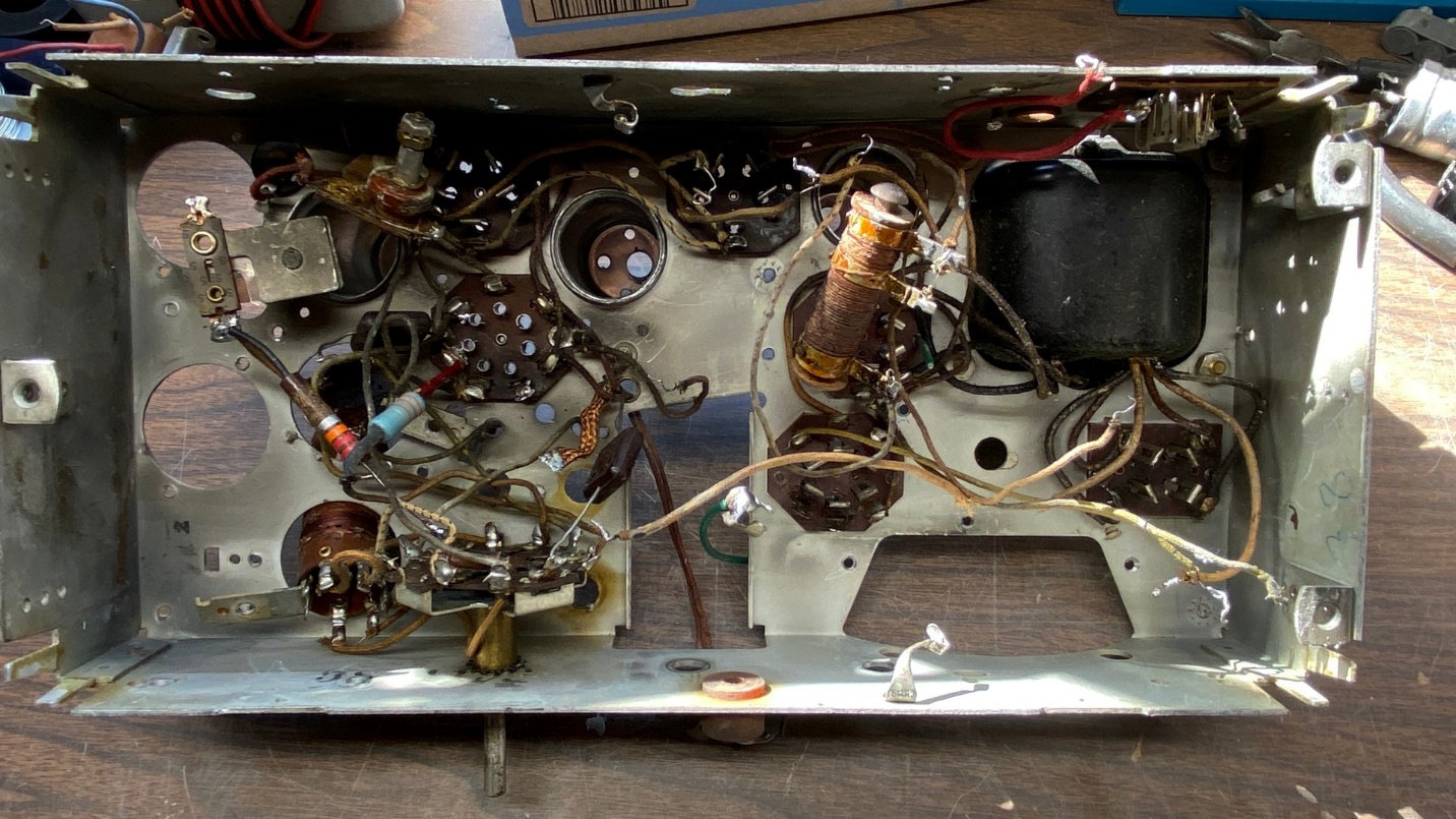
Looking under the chassis with all IF transformers removed. It’s looking sort of bare under here at this point.
Now it was time to start putting the radio back together.
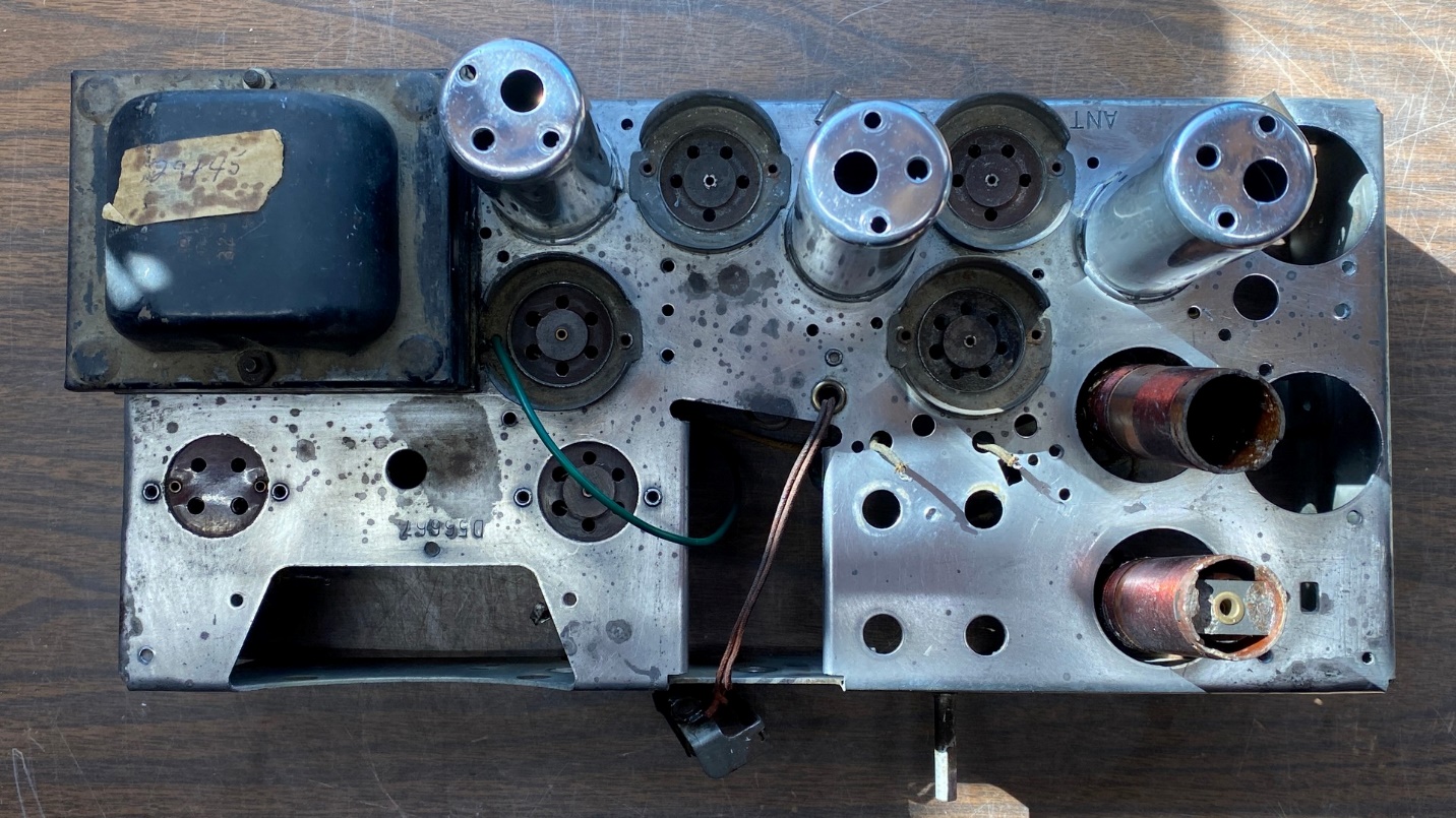
The cleaned and polished coil shields are back in place on the chassis.
I decided to start at the 6A7 tube socket and replace a couple components and possibly a few wires. The previous repair person had sloppily soldered a resistor onto the solder terminal for pin 4 of the 6A7. Apparently, in doing so the person must have flexed the thin metal quite a bit, for when I attempted to remove the resistor from the terminal, the terminal broke!
Thinking – but not saying – a few choice words, I knew I would have to replace the socket.
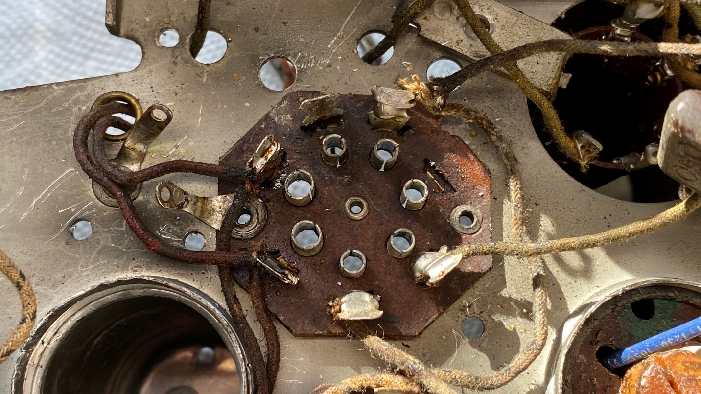
A broken terminal on this tube socket means the socket will have to be replaced.
Fortunately, I had removed an identical seven-pin tube socket from another mid-1930s Philco in the past. I found it in a drawer where I keep spare tube sockets. It was the only one I had, and it appeared to be in good shape.
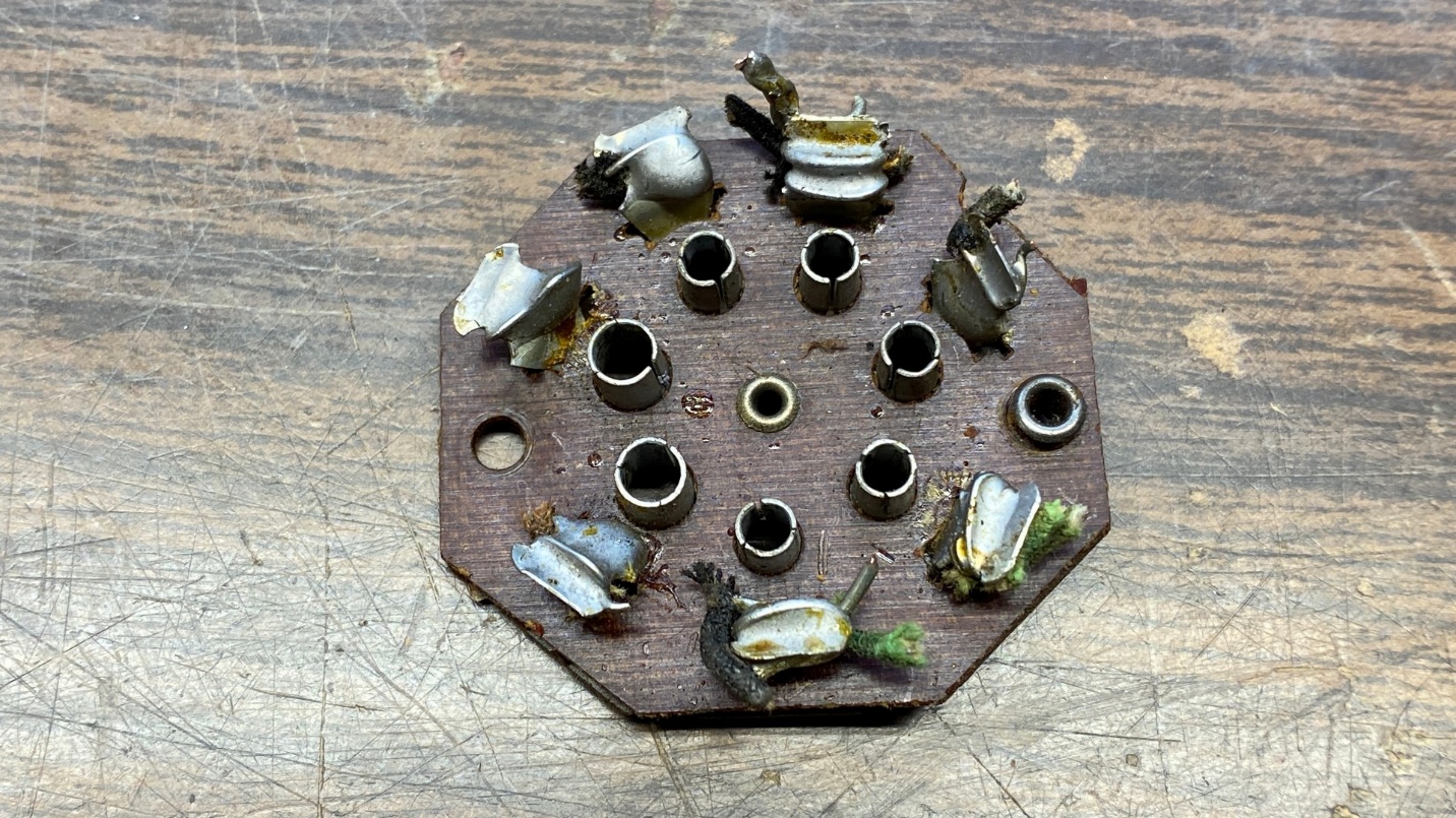
Fortunately, I had an identical seven pin socket in my archives.
I unsoldered and removed the remaining wires on the 6A7 socket. Next, working as carefully as I could, I unsoldered each of the seven terminals on the replacement socket and removed each of the wire stubs. After this, I drilled out the rivets holding the 6A7 socket – and the tube shield base – in place on the chassis.
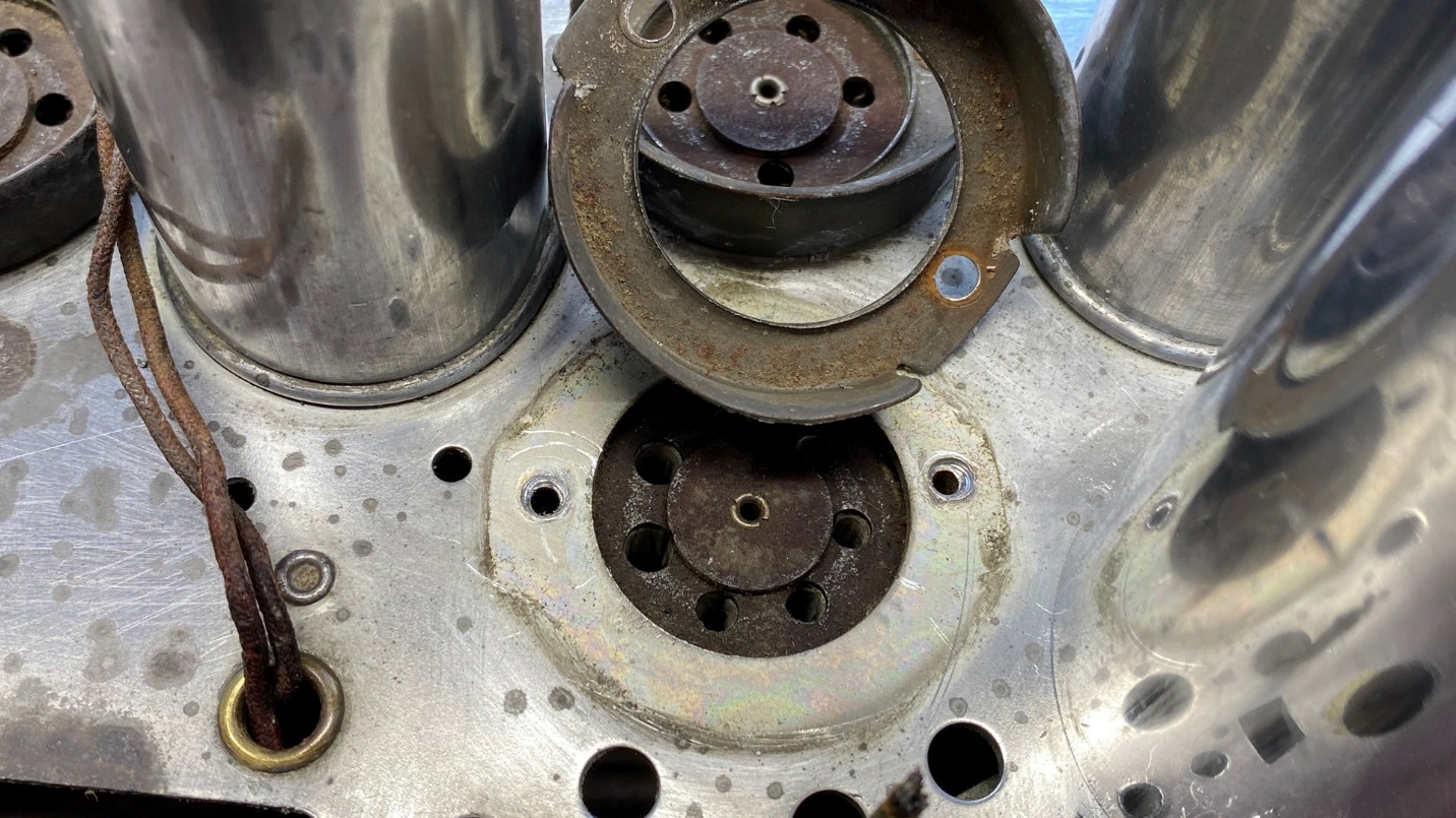
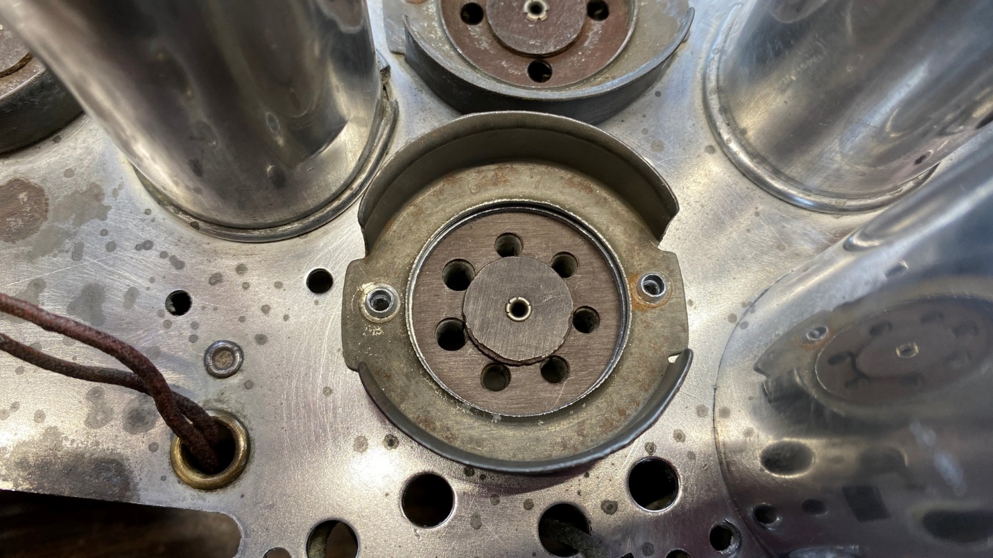
The rivets holding the 6A7 tube socket and its tube shield base have been drilled out just enough to permit removal of the socket.
I thought about how I wanted to fasten the replacement socket on the chassis. At the same time, I wondered if I should even bother reattaching the tube shield base. Philco generally stopped using a tube shield over the 6A7 first detector tubes in the 1936 season, as they had found the shields were not really needed on that particular tube. However, to keep the chassis looking original, I went ahead and reused the tube shield base.
The replacement socket, along with the tube shield base, have been reattached to the chassis with pop rivets.
I used pop rivets to fasten the replacement socket and tube shield base onto the chassis.
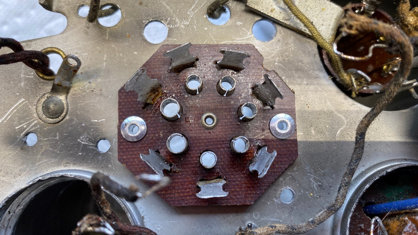
Bottom view of the replacement socket.
You may have noticed in a previous photo that there had been a grounding lug riveted between the heater terminals of the 6A7. I decided not to replace this lug since there was another one mounted on the chassis, very close to the lug which I did not replace. The lug that had been mounted on the tube socket had only one wire attached to it. I felt that I could easily transfer that wire to the other solder lug, along with one end of a ceramic C0G/NP0 capacitor (which would replace a mica capacitor) and a piece of copper braiding, the other end of which would be soldered to one of the mounting bolts of the tuning condenser.
I’m running out of space again, so I will continue the saga of the Philco 29 chassis next time. Until then!